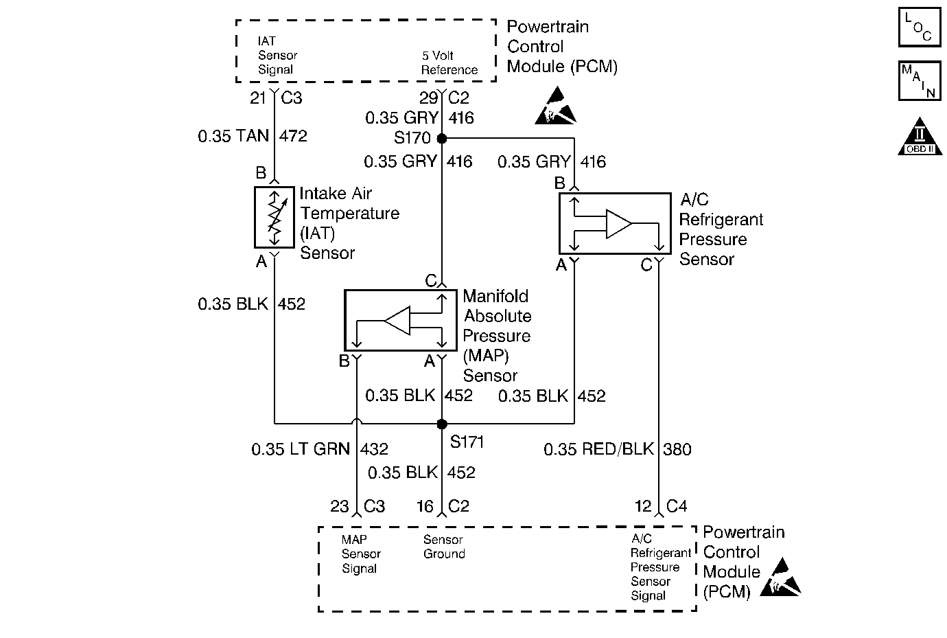
Circuit Description
The PCM can determine if the A/C clutch is engaged or not engaged through the A/C clutch status line. If the PCM has grounded the A/C relay control circuit, current can flow through the A/C relay to the A/C compressor clutch and back to the PCM on the A/C status circuit.
The PCM monitors the A/C clutch status circuit and can determine when the clutch has cycle from ON to OFF. As the A/C compressor cycles OFF, the PCM will record A/C refrigerant pressure from the A/C refrigerant pressure sensor. If the PCM does not detect an increase from the A/C refrigerant pressure sensor when the A/C clutch cycles back ON, a DTC P0531 will set. This condition can occur if the A/C refrigerant pressure sensor is fixed at one value.
Conditions for Setting the DTC
The PCM does not detect an A/C refrigerant pressure change of more than 4.0 psi when the A/C clutch has been cycled OFF for 10.0 seconds, then ON for 10.0 seconds.
Action Taken When the DTC Sets
| • | The DTC will be stored in the PCM memory when the diagnostic runs and fails. |
| • | The Malfunction Indicator Lamp (MIL) will not illuminate. |
| • | The PCM will record operating conditions at the time the diagnostic fails. This information will be stored in Failure Records. |
Conditions for Clearing the MIL/DTC
| • | A history DTC will clear after 40 consecutive warm-up cycles, if no failures are reported by this or any other non-emission related diagnostic. |
| • | A last test failed (Current DTC) will clear when the diagnostic runs and does not fail. |
| • | PCM battery voltage is interrupted. |
| • | Using a scan tool. |
Diagnostic Aids
Inspect the harness going to the A/C clutch and going to the PCM for intermittent connections. While the engine is operating with the A/C enabled, move related electrical connectors and harnesses. This may aid in locating an intermittent fault. The scan tool failure records buffer feature my also help locate a fault. Drive the vehicle in the conditions that were noted from failure record data.
For intermittents, refer to Symptoms .
Test Description
Number(s) below refer to step numbers on the diagnostic table.
-
Checks if the PCM is able to turn the A/C compressor ON.
-
Checks for an A/C refrigerant pressure sensor that is at a fixed value (stuck).
-
An intermittent open A/C clutch status circuit, can cause the PCM to wrongly detect the A/C clutch cycling. When the PCM falsely detects the clutch cycling ON and OFF and the clutch is remaining ON, a DTC P0531 will set since no refrigerant pressure change was detected. So before replacing the A/C refrigerant pressure sensor, inspect the A/C clutch status circuit.
-
If the scan tool indicates that the A/C clutch is ON, check connections at the compressor first.
-
If the B+ supply circuit to the A/C relay is intermittent, the PCM A/C clutch status circuit may not detect voltage when A/C is commanded ON. So inspect relay connections and operation.
Step | Action | Value(s) | Yes | No |
|---|---|---|---|---|
1 | Was the Powertrain On-Board Diagnostic (OBD) System Check performed? | -- | ||
|
Important: If DTCs P0530, P1545, and P1546 are set, use those tables.
Does the A/C clutch engage? | -- | |||
Did the A/C High Side pressure increase more than the specified value when the A/C controls were turned ON? | 4 psi | Go to Diagnostic Aids | ||
Repair the faulty A/C refrigerant pressure sensor connection or faulty sensor. Is the action complete? | -- | -- | ||
Does the scan tool indicate A/C clutch ON? | -- | |||
Repair intermittent A/C clutch circuit from the A/C relay to the splice. Is the action complete? | -- | -- | ||
7 |
Does the test light illuminate? | -- | ||
8 | Using a test light, probe the A/C compressor clutch B+ supply circuit to the A/C compressor clutch ground circuit. Does the test light illuminate? | -- | ||
9 | Repair the faulty A/C clutch connection or open A/C clutch coil. Is the action complete? | -- | -- | |
10 | Repair the open or shorted A/C clutch B+ supply circuit. Is the action complete? | -- | -- | |
11 | Repair the open A/C clutch ground circuit. Is the action complete? | -- | -- | |
12 |
Does the scan tool indicate that this test ran and passed? | -- | ||
13 | Using the scan tool, select Capture Info, Review Info. Are any DTCs displayed that have not been diagnosed? | -- | Go to the applicable DTC table | System OK |
