Removal Procedure

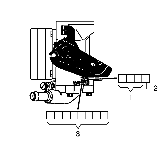
An eight-digit part identification number (3) is stamped on the throttle
body casting. Refer to this number if servicing, or part replacement is required.
A build date is stamped on the throttle body which indicates the day
of year (1) and the year (2) that the throttle body was manufactured.

- Disconnect the negative battery cable.
- Partially drain the cooling system.
- Disconnect the electrical connectors from the TP sensor, IAC valve,
IAT sensor and the MAF sensor.
- Remove the air intake duct with the MAF sensor.
- Disconnect the crankcase ventilation hose and the EVAP canister
purge solenoid valve vacuum hose from the throttle body.
- Disconnect the coolant hoses from the throttle body.
- Disconnect the accelerator control cable from the throttle body.
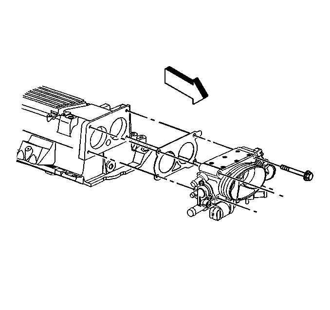
- Remove the throttle body attaching bolts.
- Remove the throttle body and the gasket. Discard the gasket.
Notice: In order to prevent damage to the sealing surfaces, carefully use sharp
tools in cleaning the old gasket from the aluminum surfaces.
Important:
| • | Do Not soak the throttle body in cold immersion type cleaner.
The throttle valves have a factory applied sealing compound (DAG material
is applied to the outside edge of each valve and the throttle bore) to prevent
air bypass at closed throttle. Strong solvents or brushing will remove the
material. To clean the throttle body following disassembly, use a spray type
cleaner such as GM X66-A or GM 1052626. Use a shop towel to remove heavy
deposits. |
| • | The TP sensor and the IAC valve are electrical components and
should NOT come in contact with solvent or cleaner, as damage may result. |
- Clean the gasket sealing surfaces.
Installation Procedure

- Install the throttle body with a new gasket.
- Install the throttle body attaching bolts.
Tighten
Tighten the throttle body attaching bolts to 25 N·m (18 lb ft).
- Connect the accelerator control cable.
- Connect the coolant hoses to the throttle body.
- Connect the EVAP canister purge solenoid valve vacuum hose and
the crankcase ventilation hose to the throttle body.
- Install the air intake duct with the MAF sensor.
- Connect the electrical connectors to the TP sensor, IAC valve,
IAT sensor, and the MAF sensor.
- Refill the cooling system.
- Connect the negative battery cable.
- With the engine OFF, check to see that the accelerator pedal is
free. Depress the accelerator pedal to the floor and release.
- Adjust the accelerator control cable. Refer to Section 5E2.
- Reset the IAC valve pintle position.
| 12.1. | Depress the accelerator pedal slightly. |
| 12.3. | Release the accelerator pedal. |
| 12.4. | Run the engine for 5 seconds. |
| 12.5. | Turn the ignition OFF for 10 seconds. |
| 12.6. | Restart the engine. |
| 12.7. | Check for proper idle operation. |
Important: If replacing the Throttle Position (TP) sensor or the throttle body,
the Electronic Brake and Traction Control Module (EBTCM) must learn the TP
sensor idle position voltage with the new component(s) installed. This is
necessary to ensure effective engine torque reduction during Acceleration
Slip Regulation (ASR) events. Perform this procedure using Techline
equipment.


