| Subject: | Vehicles Built Without RKE (Remote Keyless Entry) |
| Models: | 1999 Chevrolet C/K Models (Suburban, 2-Door Tahoe) |
| Built Between 11/23/98 and 12/4/98 without RPO AU0 (Remote Keyless Entry) |
A limited number of the above vehicles were produced without option
AU0 (Remote Keyless Entry). The original window label and invoice REFLECTED
THE REDUCED PRICE. As a result, customers have been notified that they can
have an aftermarket RKE installed for $100.00. This represents a savings
to the customer of $50.00 over the MSRP pricing. For those owners who already
paid to have the aftermarket RKE installed, reimburse the owner $50.00.
Service Procedure
Install GMSPO RKE unit, using the following procedure:
Important: Follow the steps of this procedure exactly, in order to properly diagnose
any needed repairs to the system.
- Roll down the driver's door window.
- Install protective seat covers.
Caution: Before servicing any electrical component, the ignition key must be
in the OFF or LOCK position and all electrical loads must be OFF, unless instructed
otherwise in these procedures. If a tool or equipment could easily come in
contact with a live exposed electrical terminal, also disconnect the negative
battery cable. Failure to follow these precautions may cause personal injury
and/or damage to the vehicle or its components.
- Disconnect the negative battery cable.
- Remove the air bag fuse 10 from the I/P fuse block.
- Remove the knee bolster from the left side of the I/P.
- Remove the knee bolster brackets.
- Disable the SIR system using the following steps.
| 7.1. | Turn the steering wheel so that the vehicle's wheels are straight
ahead. |
| 7.2. | Put the ignition switch in the "locked" position. |
| 7.3. | Remove the key from the lock cylinder. |

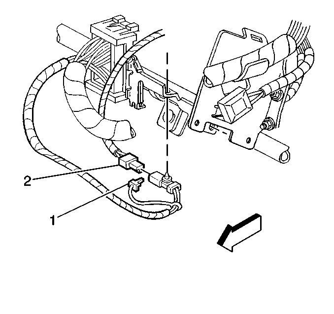
| 7.4. | Remove the Connector Position Assurance (CPA)
(1) from the driver yellow 2-way connector located at the base of the steering
column. |
| 7.5. | Disconnect the driver yellow 2-way connector (2) located at the
base of the steering column. |

| 7.6. | Remove the CPA (1) from the passenger yellow
2-way connector located at the base of the steering column. |
| 7.7. | Disconnect the passenger yellow 2-way connector (2) located at
the base of the steering column. |
Important: The thin black wire attached to the receiver module is the receiver
module antenna. It is not serviced separately. Handle the wire carefully.
- Remove the 4 screws holding the top cover of the RKE module. Remove
the cover.
- Locate the short yellow wire loop in the module. Cut the yellow
wire and trim it as close as possible to the circuit board.
- Reinstall the cover. Secure the cover with the 4 screws.
- Using a plastic tie strap from the kit, tie the RKE module to
the right side of the chime module, at the top of the convenience center.
- Remove the left cowl kick panel trim.
- Trim the following wires from the RKE wiring harness 12-way connector.
Trim the wires short and tape the wires.
- Wrap the following wires (the full length) with tape from the
8-way connector.
- Trim the following wires from the RKE wiring harness 8-way connector.
Trim the wires short and tape the wires.
- Connect the 8-way wire harness connector into the RKE module.
The following steps refer to illustrations and connector views found
in the 1999 C/K Service Manual.
- Locate connector C209. Refer to Inline Harness Connector End Views
in the Wiring System sub-section of Body & Accessories for the 1999 Suburban.
Route the purple/black, green/black and blue/black wires from the RKE connector
to connector C209 using the following steps:
| 17.1. | Remove the terminal from cavity A of connector C209. The wire
should be orange. Cut the present terminal off the wire you just removed.
Using terminal 12020116, connect the purple/black and the orange wires together.
Insert the terminal into cavity A. |
| 17.2. | Remove the terminal from cavity E of connector C209. The wire
should be light blue. Cut the present terminal off the wire you just removed.
Using terminal 12020116, connect the green/black and the light blue wires
together. Insert the terminal into cavity E. |
| 17.3. | Remove the terminal from cavity B of connector C209. The wire
should be white. Cut the present terminal off the wire you just removed. Using
terminal 12020116, connect the blue/black and white wires together. Insert
the terminal into cavity B. |
- Wrap the following wires (the full length) with tape from the
12-way connector.
- Connect the 12-way connector to the RKE module.
- Locate G200 ground. Refer to the Inline Harness Connector End
Views in the Wiring System sub-section of Body & Accessories for the 1999 Suburban.
Route the black/white wire from the RKE module 8-way and black wire
from the 12-way connectors to G200. Install the kit supplied "Eyelet"
terminal to these wires. Install the wires in the I/P at the G200 location.
- Locate connector C298. Refer to the Inline Harness Connector End
Views in the Wiring System sub-section of Body & Accessories for the 1999 Suburban.
The connector may be white rather than black as shown in the Service Manual.
Its location is between the convenience center and the headlight switch. Route
the black/white wire from the 12 cavity RKE connector to connector
C298. Remove the terminal from cavity C of C298. The wire should be white
in color. Cut the present terminal off the wire you just removed. Using terminal
12092344, connect the black/white and the white wires together. Insert the
terminal into cavity C.
- Locate the steering column connector. Refer to the Inline Harness
Connector End Views in the Wiring System sub-section of Body & Accessories
for the 1999 Suburban. Route the red, yellow and brown wires from the
RKE module connector to the steering column connector using the following
steps:
| 22.1. | Locate the pink wire in cavity A2. Splice the pink and yellow
wires together using the kit supplied connector. |
| 22.2. | Locate the black wire in cavity A11. Splice the brown and black
wires together using the kit supplied connector. |
| 22.3. | Remove the terminal from cavity D2. The wire should be red in
color. Cut the present terminal off the wire you just removed. Using terminal
12020116, connect the 2 red wires together. Insert the terminal into cavity
D2. |
Important: Route all wires away from the sharp metal brackets. Make sure they are
properly secured.
- Verify the functionality of the system using the following procedure.
Its operation is somewhat different than the production-installed system.
| 23.1. | Connect the negative battery cable. |
| 23.2. | Depress the lock button. The following actions should occur: |
| • | The interior lamps remain ON for 20-30 seconds and then
go out. |
| 23.3. | Depress the unlock button. The following actions should occur: |
| 23.4. | Depress the horn button (panic mode) for 1.5 seconds. The
horn should honk for 30 seconds. To exit the panic mode, depress the
lock, unlock or horn button. |
| 23.5. | Depress the GM button for less than a second. This turns off the
horn when the doors are locked or unlocked (temporarily), this time only. |
- Enable the SIR system using the following steps:

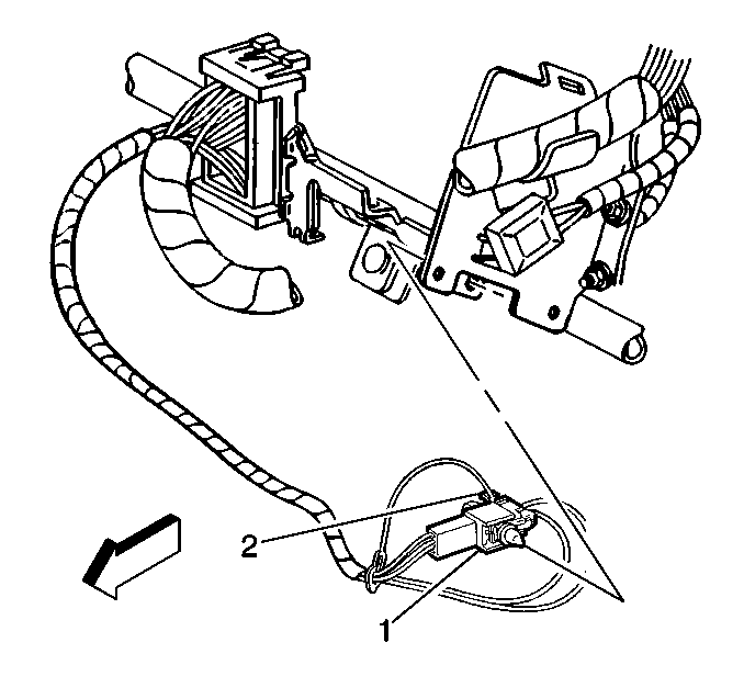
| 24.1. | Connect the driver yellow 2-way connector (2)
located at the base of the steering column. |
| 24.2. | Connect the CPA (1) from the driver yellow 2-way connector located
at the base of the steering column. |

| 24.3. | Connect the passenger yellow 2-way connector
(2) located at the base of the steering column. |
| 24.4. | Connect the CPA (1) from the passenger yellow 2-way connector
located at the base of the steering column. |
- Replace the left cowl trim.
- Replace the knee bolster bracket.
- Replace the knee bolster.
- Replace the air bag fuse 10 in the I/P fuse block.
- Remove the protective seat covers.
- Make a copy of the following form. Cut it to size and place it
in the vehicle's Owner's Manual.
REMOTE KEYLESS SYSTEM OPERATIONAL FEATURES ADDED TO THIS
VEHICLE
|
ACTION
| RESULT
|
Depress the lock button
|
| • | The interior lamps remain ON for 20-30 seconds and then
go out. |
|
Depress the unlock button
|
|
Depress the horn button (panic mode) for 1.5 seconds
|
| • | The horn honks for 30 seconds. |
| • | To exit (panic mode), depress the lock, unlock or horn button. |
|
Depress the GM button for less than a second
| This turns
off the horn when the doors are locked or unlocked (temporarily), one time
only.
|
Parts Information
Part Number
| Description
| Qty.
|
12495638
| GM Accessories Module Pkg.
| 1
|
12092344
| Terminal
| 1
|
Parts are currently available from GMSPO.
Warranty Information
Claim Information
The intent of this bulletin is to install the remote keyless entry system
for the customer at a cost of $100.00. Refer to the information below for
claim submission for customer reimbursement if remote keyless entry was previously
installed.
Repair Performed
| Part Count
| Part No.
| Parts Allow
| CC-FC
| Labor Op
| Labor Hours
| Net Item
|
Install keyless entry
| N/A
| N/A
| N/A
| MK-95
| Z2031
| 1.3 hrs
| 25.30*
|
Customer reimbursement for RKE installation
| N/A
| N/A
| N/A
| MK-95
| Z2031
| 0.2 hr
| 50.00**
|
N/A -- not applicable
*The amount identified in the "Net Item" column represents
the total parts cost plus the 40% markup less the $100.00 received from the
customer.
**Reimbursement to the owner of $50.00
Reimbursement
Consideration for reimbursement for RKE installation will be allowed
only if genuine General Motors parts were used. The amount to be reimbursed
will be limited to $50.00 and the process for claim submission for this reimbursement
is the same as stated in the above table.
When a customer requests reimbursement, they must provide the following:
| • | Proof of ownership at the time of installation. |
| • | Original paid receipt confirming the amount and description of
the installation of RKE and the person or entity performing the installation. |


