OIL PRESS SWITCH LOCATIONS INFORMATION / THM 700-R4

Model and Year ALL THM 700-R4
This bulletin is reissued to cover part number changes, part number identification color code revisions, and graphic illustration revisions. Bulletin 83-96 dated october, 1983 should be destroyed.
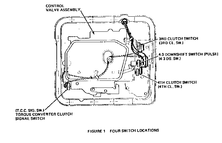
The THM 700-R4 transmission has four (4) oil pressure switch locations in the control valve assembly (see Figure 1).
Depending on vehicle type, various oil pressure switches will be used in these locations. When no switch is used, a 1/8 inch NPT pipe plug, P/N 444612, is installed in place of the switch.
On vehicles built without an electronic control module (ECM) these switches control the torque converter clutch operation and exhaust gas recirculation (EGR) bleed system. On ECM equipped vehicles these switches help supply information to the ECM about the transmission operation. The ECM also controls various functions including fuel mixture, engine timing, engine idle, and torque converter clutch (TCC) operation. If switches are wrong, mislocated, or malfunction, various electrical and mechanical problems may result, i.e., blown fuses, instrument panel lights remaining on without ap- parent reason, or improper engine operation.
GENERAL SWITCH DESCRIPTION
Oil pressure switches are activated by hydraulic pressure from the control valve assembly. Depending on design, a switch may function as the ground for an electrical circuit or as a simple connecting switch. All switches are designed to be either normally open (N.O.) or normally closed (N.C.).
N.O. - Means the switch will not allow electric current to flow until the switch is activated by hydraulic pressure.
N.C. - Means the switch will allow electric current to flow until the switch is activated by hydraulic pressure.
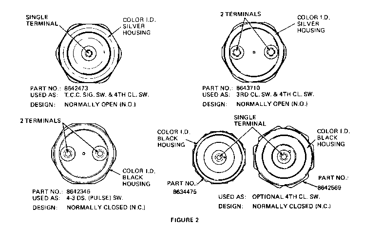
Also, the switches may be designed with either one or two terminals (see Figure 2). Single terminal switches are used to provide an electrical ground while two terminal switches act as connecting switches.
SPECIFIC SWITCH FUNCTION
1. "Torque Converter Signal" Switch (P/N 8642473)
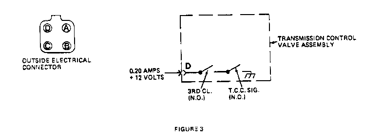
This is a single terminal normally open switch. The function of this switch is to make an electrical ground when the converter clutch is applied and break the ground when the clutch is released. For all 1982 and 1983 non-ECM vehicles with TCC signal, this switch is wired in series with the 3rd clutch switch (see Figure 3).
2. 3rd Clutch Switch (P/N 8643710)
This is a two-terminal normally open switch. It is currently wired in series with the TCC signal switch and allows current to flow to the TCC signal switch only when the transmission is in third gear, although the high altitude option is an exception. The combined function of the 3rd clutch switch and the TCC switch is as follows:
Twelve (12) volts D.C. 0.20 amp electric current is sent across the EGR solenoid (60 ). With either switch open, the current cannot flow. This signals the EGR solenoid that the transmission is not in third gear and that the converter clutch is released. When the transmission is in third gear and the converter clutch is applied, the electrical current from the EGR solenoid flows through the 3rd clutch switch and grounds through the TCC signal switch. This signals the EGR solenoid to release emission control (see Figure 3).
3. 4-3 Downshift Switch (P/N 8642346)
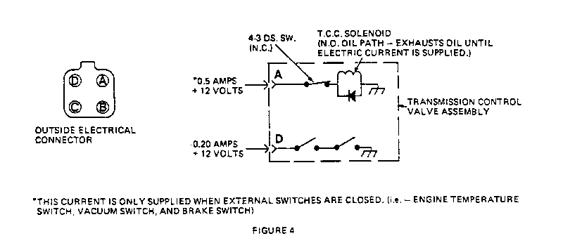
This is a normally closed two terminal switch. The 4-3 downshift switch is sometimes referred to as a pulse switch and performs the function of releasing the converter clutch when a 4-3 downshift is made (see Figure 4). The 4-3 downshift switch is activated by exhaust oil from the 4th clutch. After the 4th clutch oil has exhausted, the switch closes and allows the converter clutch to reapply. This momentary release (pulse) of the converter clutch allows the transmission to make a 4-3 downshift without any objectional shift feel.
4. 4th Clutch Switch
One of three different switches may be installed in this location depending on vehicle usage.
A. 4th Clutch Switch (P/N 8643710)
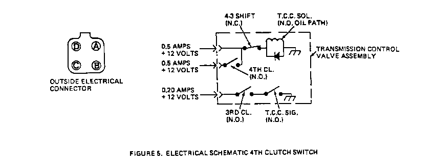
This switch is a normally open two terminal switch. The function of this switch is to keep the converter clutch applied in 4th gear regardless of engine vacuum (see Figure 5).
B. 4th Clutch Switch (P/N 8634475 or P/N 8642569)
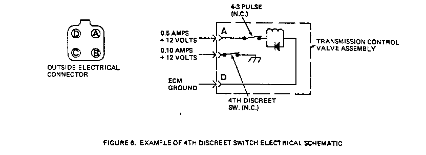
These are normally closed single terminal switches. They are used in vehicles with ECM's. The purpose of either switch is to signal the ECM when the vehicle is in 4th gear (see Figure 6).
C. Fourth Clutch Switch (P/N 8642473)
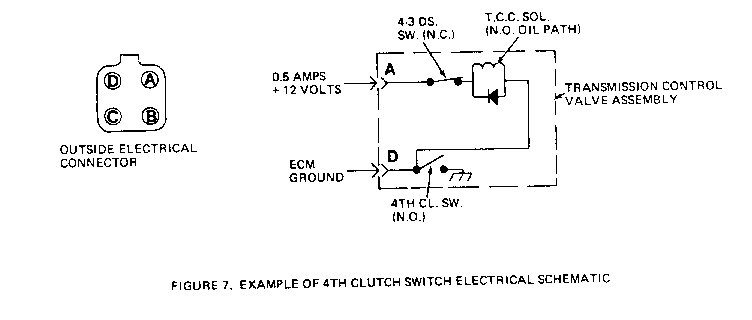
This is a normally open single terminal switch. The function of this switch is to keep the converter clutch applied in fourth gear regardless of any other controls (see Figure 7).
The following procedure may be used in diagnosing the oil pressure switches:
OIL PRESSURE SWITCH CHECKING PROCEDURE
TOOLS REQUIRED: AIR LINE ADJUSTABLE TO 60 PSI BATTERY POWERED TEST LIGHT
Switch Type Part No. Step: Action Result
Single Terminal 8642473 1: Connect test light leads 1: Light off Nomally open Silver to the teminal and switch Housihg body; air pressure <10 psi 2: Apply air pressure to the 2: Light on switch; air pressure >30 psi Single Terminal 8634475 1: Connect test light leads 1: Light on Nomally closed 8642569 to the teminal and switch Black, body; air pressure <30 psi Housing 2: Apply air pressure to the 2: Light off switch; air pressure >55 psi Double Terminal 8643710 1: Connect the test light 1: Light off Nomally open Silver leads to the switch Housing terminals; air pressure <10 psi 2: Apply air pressure to the 2: Light on switch; air pressure >30 psi Double Terminal 8642346 1: Connect the test light 1: Light on Normally closed Black leads to the switch Housing terminals; air pressure <7 psi 2: Apply air pressure to the 2: Light off switch; air pressure >14 psi
Provided below is a chart that shows specific switches required for the various types of transmission usages. Refer to your service manual for wiring diagrams of each vehicle type if needed.
VEHICLE TYPE AND SWITCHES REQUIRED
T TCC SIG SW 3RD CL SW 4-3 DS SW 4TH CL SW - ---------- --------- --------- --------- 1 8642473 8643710 8642346 8643710
2 Plug Plug 8642346 8643710
3 Plug Plug 8642346 Plug
4 Plug Plug 8642346 8634475(8642569)
5 8642473 8643710 8642346 8642473
6 Plug Plug Plug Plug
7 8642473 Plug Plug 8643710
8 Plug Plug Plug 8643710 9 Plug Plug Plug 8634475(8642569) 10 Plug Plug 8642346 8642473
General Motors bulletins are intended for use by professional technicians, not a "do-it-yourselfer". They are written to inform those technicians of conditions that may occur on some vehicles, or to provide information that could assist in the proper service of a vehicle. Properly trained technicians have the equipment, tools, safety instructions and know-how to do a job properly and safely. If a condition is described, do not assume that the bulletin applies to your vehicle, or that your vehicle will have that condition. See a General Motors dealer servicing your brand of General Motors vehicle for information on whether your vehicle may benefit from the information.
