For 1990-2009 cars only
Removal Procedure
Tools Required
J 24319-01 Steering Linkage Puller
- Raise and support the vehicle. Refer to Vehicle Lifting and Jacking in General Information in the 1999 C/K Truck Service Manual.
- Remove the steering shock absorber from the relay rod, if equipped. Refer to Steering Shock Absorber Replacement in Steering in the 1999 C/K Truck Service Manual.
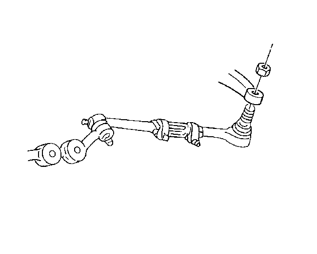
- Remove the inner tie rod ball joint from the relay rod. Refer to Tie Rod Replacement .
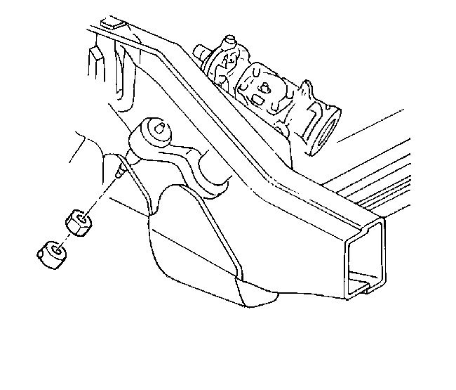
- Remove the idler arm ball stud nut. Do not reuse the nut.
- Remove the pitman arm nut. Do not reuse the nut.
- Use the J 24319-01 in order to remove the idler arm ball stud from the relay rod.
- Use the J 24319-01 in order to remove the pitman arm ball stud from the relay rod.
- Inspect the threads on the ball stud.
- Clean the threads on the ball stud.
- Inspect the ball stud seals for excessive wear.
Installation Procedure
Tools Required
| • | J 29193 Steering Linkage Installer (12 mm) |
| • | J 29194 Steering Linkage Installer (14 mm) |
- Install the idler arm ball stud to the relay rod.
- Install the pitman arm ball stud to the relay rod. Ensure that the seal is on the stud.
- Remove the tool.
- Install the new nut to the idler arm.
- Install the new nut to the pitman arm.
- Install the tie rod inner ball joints to the relay rod. Refer to Tie Rod Replacement .
- Install the steering shock absorber to the relay rod, if equipped. Refer to Steering Shock Absorber Replacement in Steering in the 1999 C/K Truck Service Manual.
- Lower the vehicle.
Tighten
Use the J 29193 or the J 29194 in order to tighten the
ball studs to 62 N·m (46 lb ft).
Tighten
Tighten the nuts to 62 N·m (46 lb ft).
