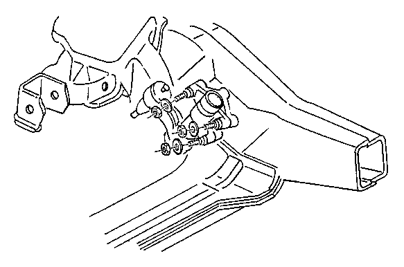
For 1990-2009 cars only
Removal Procedure
Tools Required
| • | J 24319-01 Steering Linkage Puller |
| • | J 29193 Steering Linkage Installer (12 mm) |
| • | J 29194 Steering Linkage Installer (14 mm) |
- Raise and suitably support the vehicle. Refer to Vehicle Lifting and Jacking in General Information in the 1999 C/K Truck Service Manual.
- Remove the bolts that secure the lower front shield.
- Remove the lower front shield.
- Remove the bolts that secure the front differential shield.
- Remove the front differential shield.
- Remove the idler arm ball stud nut. Do not reuse the nut.
- Use the J 24319-01 in order to remove the idler arm from the relay rod.
- Inspect and clean the ball stud threads for damage, and inspect the ball stud seal for cuts or other damage.
NOTICE: Do not attempt to free the ball stud by using a pickle fork or a wedge-type tool. Seal or bushing damage could result. Use the proper tool in order to separate all the ball joints.

Installation Procedure
- Position the idler arm mounting bracket on the frame.
- Install the frame bolts and the nuts to the idler arm.
- Install the idler arm ball stud to the relay rod.
- Remove the tool.
- Install the new nut to the idler arm ball stud.
- Lower the vehicle.
- Adjust the front toe. Refer to Measuring Wheel Alignment K Model in Wheel Alignment in the 1999 C/K Truck Service Manual.

Tighten
Tighten the frame bolts to 99 N·m (73 lb ft).
Tighten
Use the J 29193 or the J 29194 in order to tighten the
ball stud to 54 N·m (40 lb ft).
Tighten
Tighten the nut to 62 N·m (46 lb ft).
