For 1990-2009 cars only
Removal Procedure
- Relieve the brake system pressure.
- Sipon the brake fluid from the hydraulic brake booster reservoir.
- Disconnect the master cylinder fluid level sensor electrical connector.
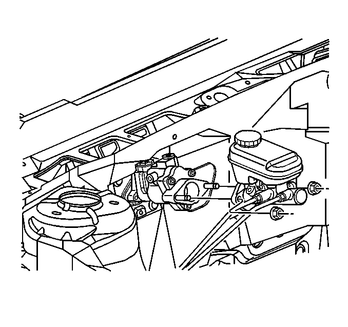
- Remove the master cylinder attaching nuts.
- Remove the master cylinder from the booster. Move the master cylinder forward to clear the studs on the booster.
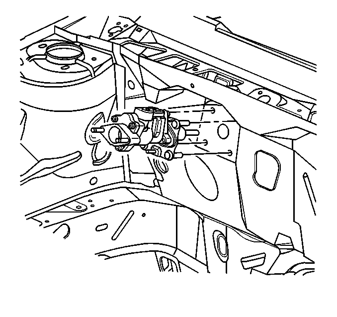
- Remove the booster attaching nuts from the brake pedal assembly.
- Disconnect the hydraulic pressure (inlet) line from the booster.
- Remove the right sound insulator. Refer to Closeout/Insulator Panel Replacement - IP Lower Right in Body and Accessories in the 1999 C/K Truck Service Manual.
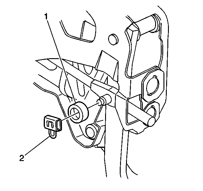
- Remove the pushrod retainer (2) and the washer (1) from the brake pedal clevis pin.
- Remove the booster pushrod from the brake pedal. Tilt the entire booster slightly to work pushrod off the pedal clevis pin without putting undue side pressure on the pushrod.
- Pull booster forward and Remove return hose clamp and hose from the booster.
- Remove the booster from the vehicle.


Installation Procedure
- Install the booster to the vehicle.
- Install the return hose and clamp on the booster.
- Install the booster pushrod to the brake pedal.
- Install the pushrod retainer (2) and the washer (1) from the brake pedal clevis pin.
- Install the right sound insulator. Refer to Closeout/Insulator Panel Replacement - IP Lower Right in Body and Accessories in the 1999 C/K Truck Service Manual.
- Install the booster attaching nuts onto the booster studs.
- Install the acoustical barrier to the booster studs (under the I/P).
- Install the master cylinder onto the booster.
- Connect the hydraulic pressure (inlet) line to the booster.
- Install the master cylinder attaching nuts.
- Fill the booster reservoir.
- Connect the fluid level sensor electrical connector.
- If the hydraulic system was opened, bleed the brake system. Refer to Hydraulic Brake System Bleeding in the 1999 C/K Truck Service Manual.


Tighten
Tighten the nuts to 27 N·m (20 lb ft).
