Steering Shaft, Lower Bearing, and Jacket - Assemble - Off Vehicle Column Shift
Assembly Procedure
| • | J 41688 Centering Sphere Installer Tool |
| • | J 23073-01 Shift Tube Installer |
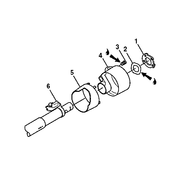
- Install the gearshift bowl shroud (5) to the gearshift lever bowl assembly (4).
- Lubricate the shift lever spring (3) with lithium grease.
- Install the shift lever spring (3).
- Lubricate the wave washer (2) with lithium grease.
- Install the wave washer (2).
- Install the lock plate (1) into the gearshift lever bowl assembly (4).
- Install the gearshift lever bowl assembly (4) to the steering column jacket assembly (6)
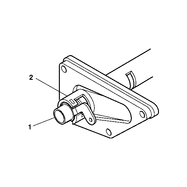
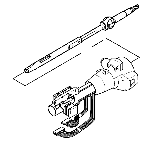
- Insert the shift tube assembly (1) through the bottom of the steering column jacket assembly (2).
- Line up the keyway from the shift tube assembly (1) with the keyway on the gearshift lever bowl assembly.
- Apply just enough pressure to extend the shift tube assembly (1) past the lock plate.
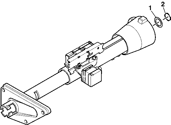
- Slide the thrust washer (1) onto the shift tube assembly.
- Slide the shift tube retaining ring (2) onto the shift tube assembly.
- Use the J 23073-01 to seat the gearshift lever bowl assembly and the shift tube retaining ring (2).
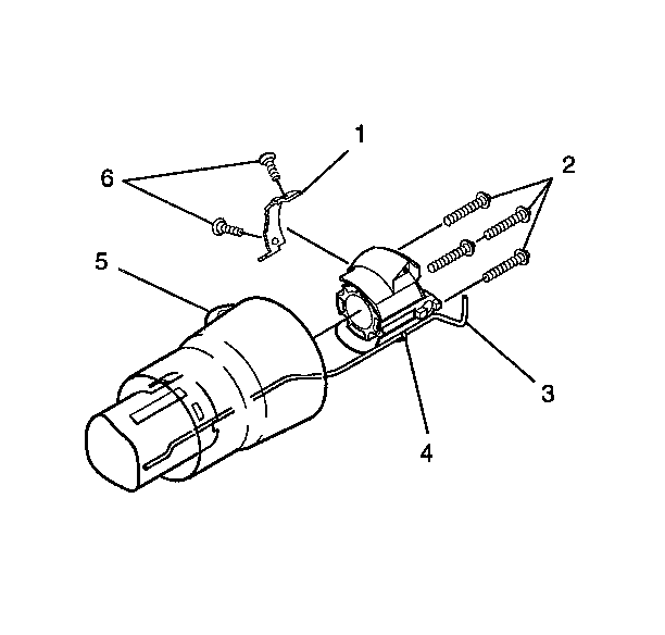
- Install the shift lever gate (1) and secure using 2 oval head cross recess screws (6).
- Install the dimmer switch actuator rod (3) into the steering column housing support (4).
- Install the steering column housing support (4) into the gearshift lever bowl assembly (5).
- Install 4 new support screws (2).
- The dimmer switch actuator rod (3) will rest in the slot on the dimmer switch assembly.
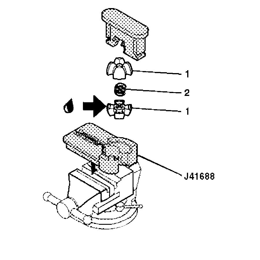
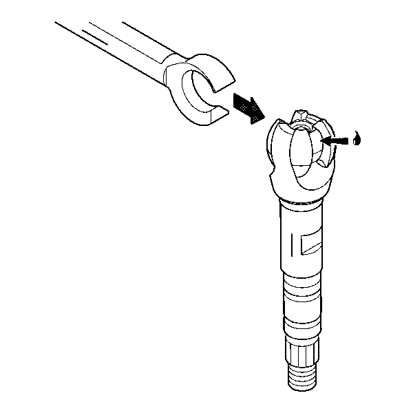
- Lubricate the inside of the centering sphere with lithium grease.
- Install the centering sphere (1) and the joint preload spring (2) into the J 41688 .
- Compress the centering sphere and the joint preload spring in J 41688 .
- Install the race and upper shaft assembly (1) to J 41688 .
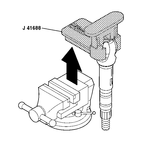
- Remove the race and upper shaft assembly with J 41688 .
- Remove the race and upper shaft assembly with the centering sphere from the J 41688 .
- Apply lithium grease to the race and upper shaft assembly (1).
- Align the marks on the race and upper shaft assembly (1) with the marks on the lower steering shaft assembly (2).
- Install the lower steering shaft assembly (2).
- Install the steering shaft assembly into the steering column jacket assembly.
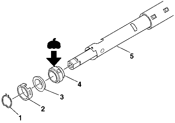
- Lubricate the inside of the lower bearing adapter (4).
- Install the lower bearing adapter (4) to the steering column jacket assembly (5).
- Install the bearing assembly (3) to the steering column jacket assembly (5).
- Install the bearing adapter retainer (2) to the steering column jacket assembly (5).
- Install the lower bearing adapter clip (1) to the steering column jacket assembly (5).
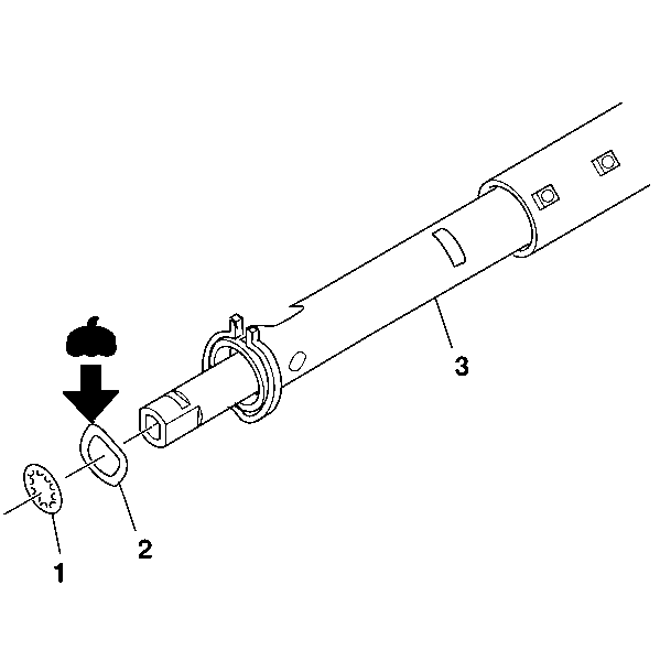
- Lubricate the bearing preload washer (2).
- Install the bearing preload washer (2) to the steering column jacket assembly (3).
- Install the new lower spring retainer (1) to the steering column jacket assembly (3).
- Install the steering column housing assembly. Refer to Steering Column Jacket - Assemble - Off Vehicle .
Notice: Use the correct fastener in the correct location. Replacement fasteners must be the correct part number for that application. Fasteners requiring replacement or fasteners requiring the use of thread locking compound or sealant are identified in the service procedure. Do not use paints, lubricants, or corrosion inhibitors on fasteners or fastener joint surfaces unless specified. These coatings affect fastener torque and joint clamping force and may damage the fastener. Use the correct tightening sequence and specifications when installing fasteners in order to avoid damage to parts and systems.
Tighten
Tighten the 2 oval head cross recess screws (6) to 3.5 N·m
(31 lb in).
Important: The support screws require a thread locking compound. New screw supports must be used when reassembling the steering column housing support (4).
Tighten
Tighten the 4 new support screws (2) to 8.5 N·m
(75 lb in).
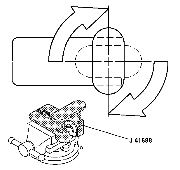
Rotate the driver of J 41688 90 degrees in the clockwise direction until the arms lock in place.
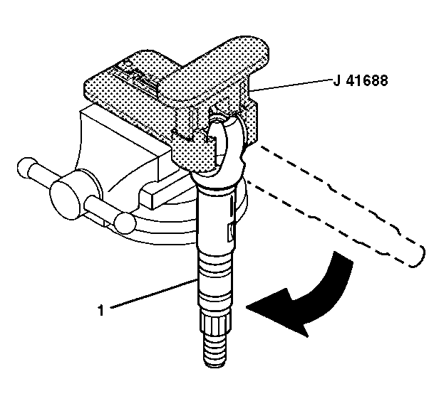
Rotate the race and upper shaft assembly (1) 90 degrees.
Steering Shaft, Lower Bearing, and Jacket - Assemble - Off Vehicle Floor Shift
Assembly Procedure
Tools Required
J 41688 Centering
Sphere Installer Tool
- Install the steering column housing shroud (7) onto the steering column housing assembly.
- Install the dimmer switch actuator rod (2) into the steering column housing support (3).
- Lubricate the key release lever spring (6).
- Install the key release lever spring (6) onto the steering column housing shroud (7).
- Install the key release lever (5) onto the steering column housing shroud (7).
- Install the lock plate (4) into the steering column housing shroud (7).
- Install 4 new support screws (2).
- The dimmer switch actuator rod (2) will rest in the slot on the dimmer switch assembly.
- Lubricate the inside of the centering sphere (1) with lithium grease.
- Install the centering sphere (1) and the joint preload spring (2) into the J 41688 .
- Compress the centering sphere and the joint preload spring in J 41688 .
- Install the race and upper shaft assembly (1).
- Remove the race and upper shaft assembly (1) with J 41688 .
- Remove the race and upper shaft assembly (1) and J 41688 from the vise.
- Rotate the race and upper shaft assembly (1) 90 degrees from J 41688 to disengage.
- Apply lithium grease to the race and upper shaft assembly (1).
- Align the marks on the race and upper shaft assembly (1) with the marks on the lower steering shaft assembly (2).
- Install the lower steering shaft assembly (2) to the race and upper shaft assembly (1).
- Install the steering shaft assembly into the steering column jacket assembly.
- Install the steering column housing assembly. Refer to Steering Column Jacket - Assemble - Off Vehicle .
- Lubricate the inside of the lower bearing adapter (4).
- Install the lower bearing adapter (4) to the steering column jacket assembly (5).
- Install the bearing assembly (3) to the steering column jacket assembly (5).
- Install the bearing adapter retainer (2) to the steering column jacket assembly (5).
- Install the lower bearing adapter clip (1) to the steering column jacket assembly (5).
- Lubricate the bearing preload washer (2).
- Install the bearing preload washer (2) to the steering column jacket assembly (5).
- Install the new lower spring retainer (1) to the steering column jacket assembly (5).
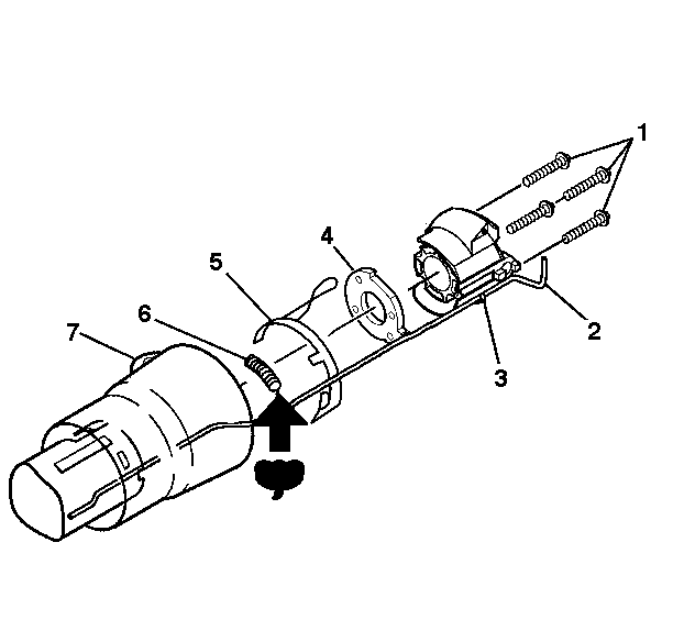
Important: The support screws require a thread locking compound. New screw supports must be used when reassembling the steering column housing support (4).
Notice: Use the correct fastener in the correct location. Replacement fasteners must be the correct part number for that application. Fasteners requiring replacement or fasteners requiring the use of thread locking compound or sealant are identified in the service procedure. Do not use paints, lubricants, or corrosion inhibitors on fasteners or fastener joint surfaces unless specified. These coatings affect fastener torque and joint clamping force and may damage the fastener. Use the correct tightening sequence and specifications when installing fasteners in order to avoid damage to parts and systems.
Tighten
Tighten the 4 new support screws (2) to 8.5 N·m
(75 lb in).
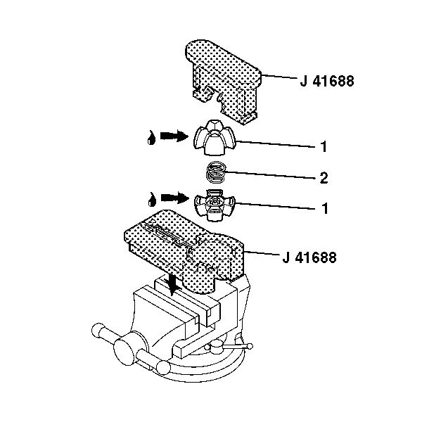

Rotate the driver of J 41688 90 degrees in the clockwise direction until the arms lock in place.

Rotate the race and upper shaft assembly (1) 90 degrees.


