Disassembly Procedure
- Remove the two screws holding the cap to the housing.
- Remove the cap from the housing.
- Remove the two screws from the rotor.
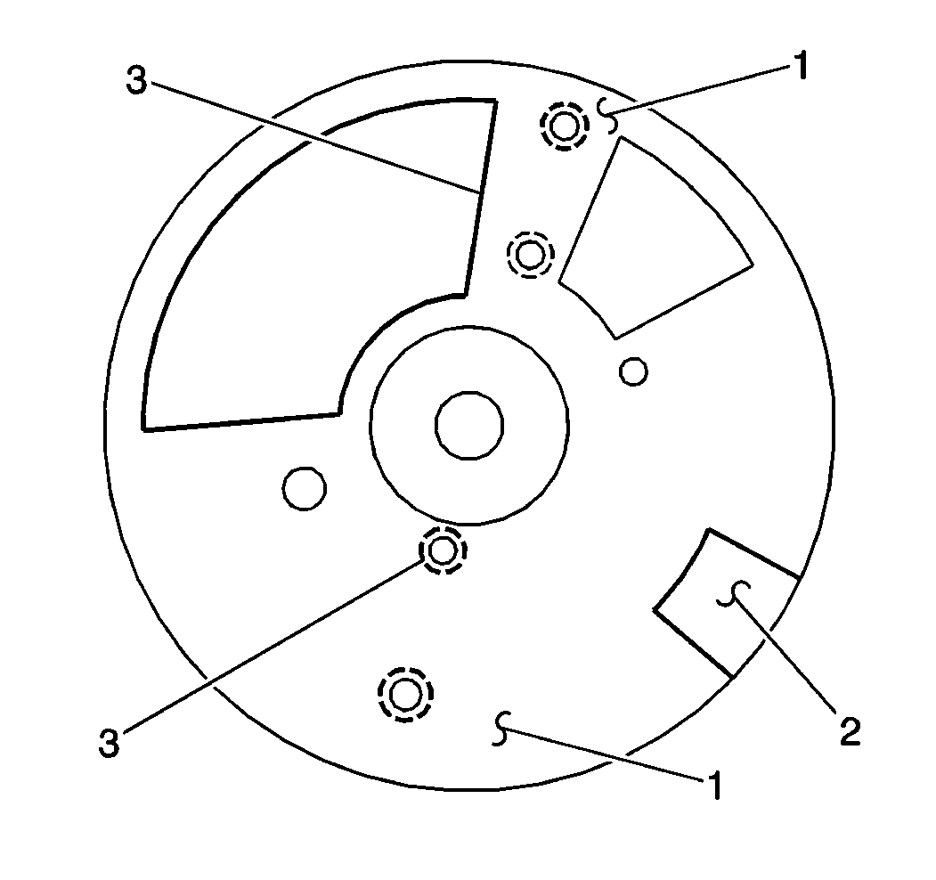
- Remove the rotor. Note from which locating holes (3) the rotor was removed.
- Remove the two screws holding the hall-effect switch.
- Make sure the square cut hole (2) in the vane wheel is aligned with the hall-effect switch.
- Remove the hall-effect switch.
- Note the dimple located below the roll pin hole on one side of the gear. Use the dimple in order to properly orient the gear on the shaft during assembly.
- Remove the roll pin from the shaft.
- From the distributor on the 5.7L engine, remove the driven gear, the washer, and the tang washer.
- From the distributor on the 7.4L engine, remove the driven gear, the washer, the tang washer, and the thermal insulator.
- Remove the shaft.
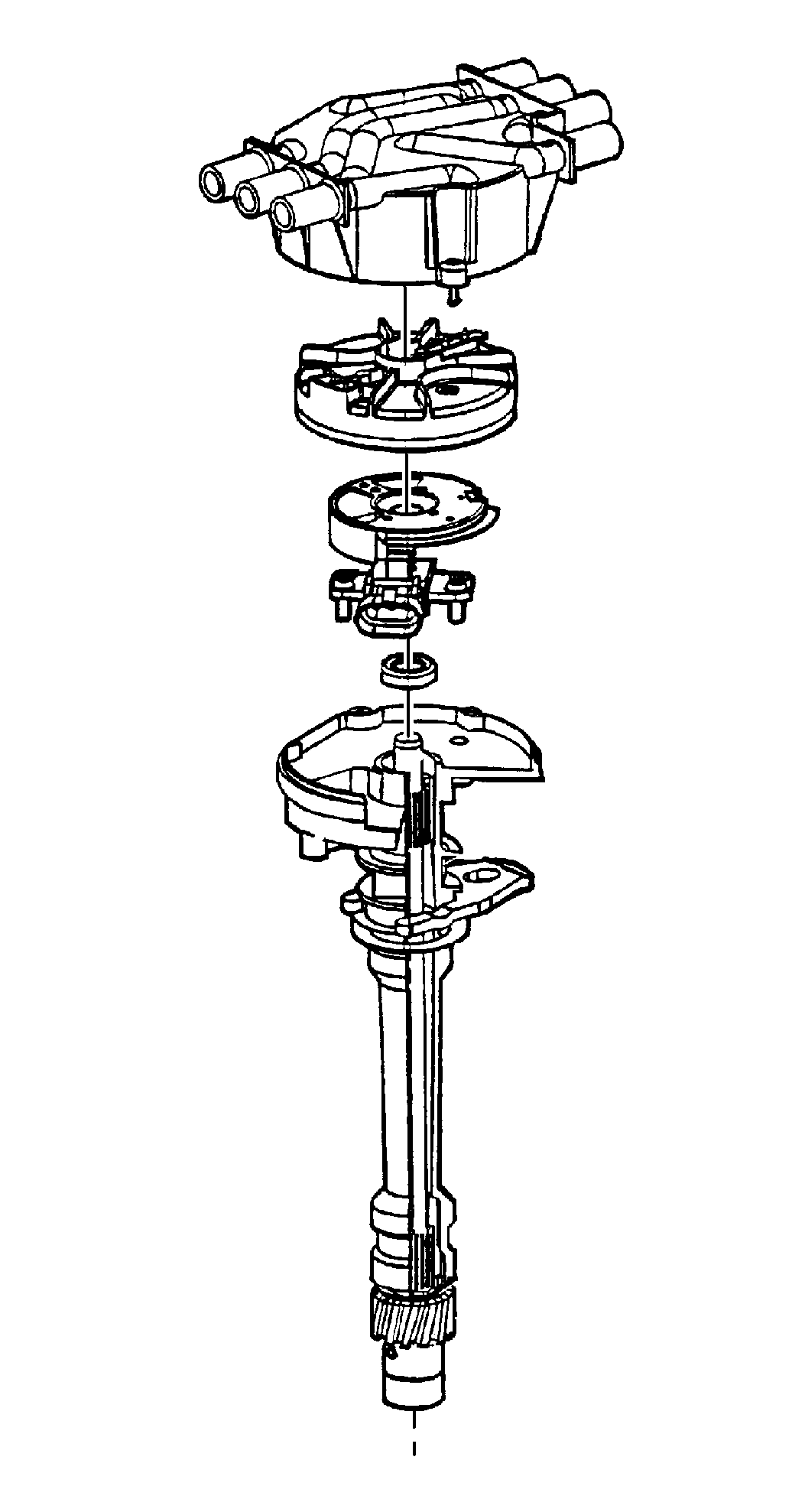
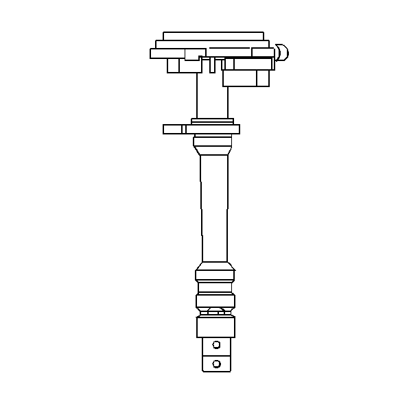
Notice: It is possible to install the distributor driven gear in two positions. Make sure when installing the gear that the dimple found below the roll pin hole in the gear is on the same side as the rotor segment. The dimple will not align directly with the rotor segment. If not, the gear is installed 180 degrees off and a no start condition may occur. Premature wear and damage may result.
Notice: Failure to keep cleaning agents away from the distributor HALL EFFECT switch may cause premature failure.
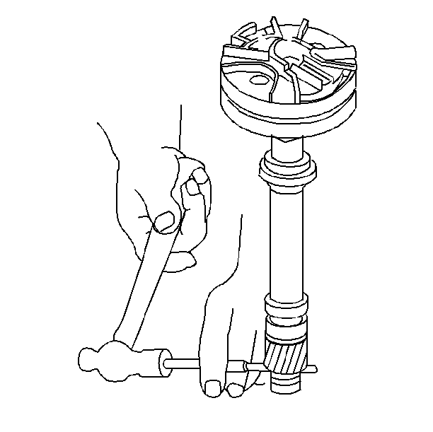
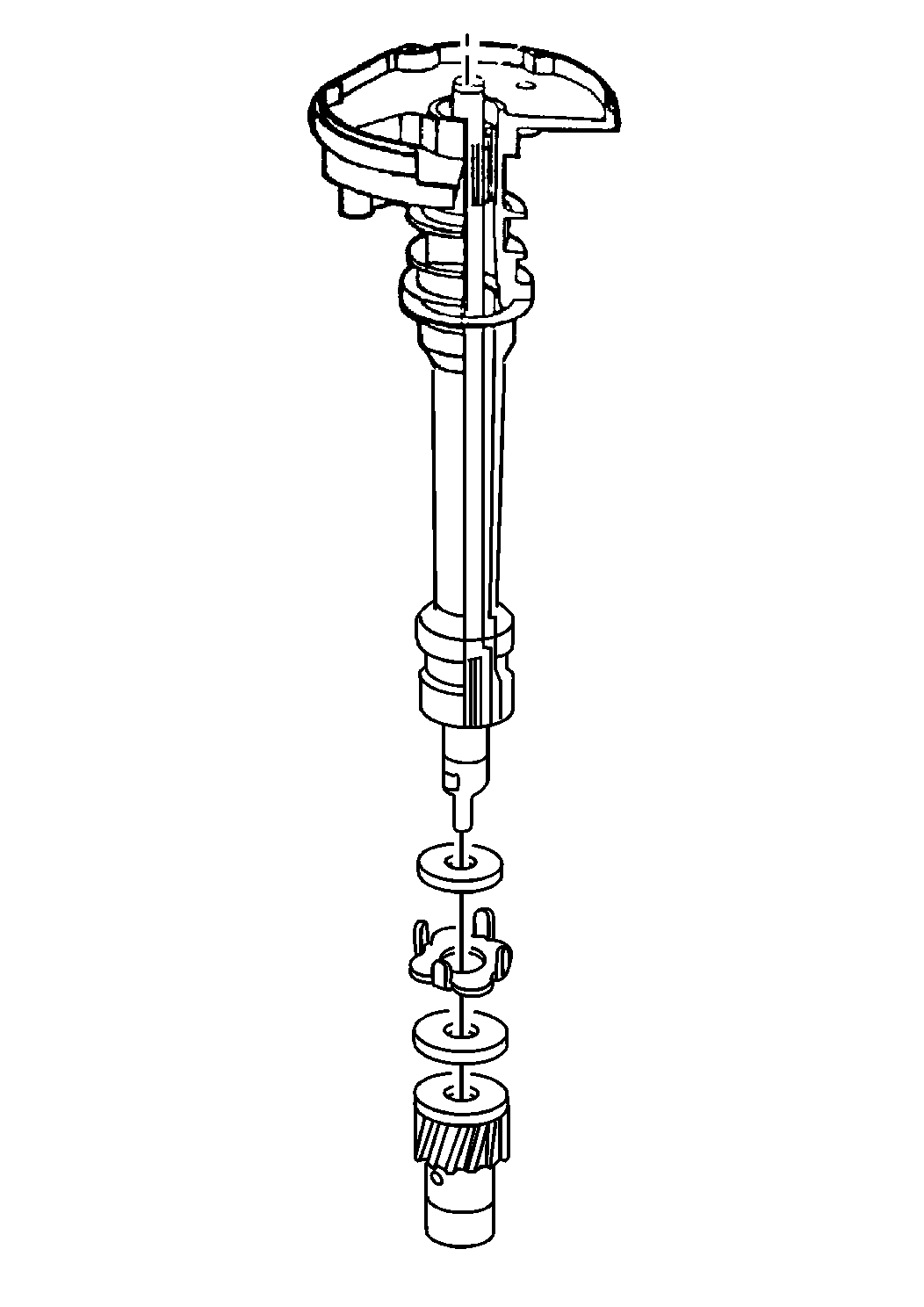
Important: If the shaft cannot be removed from the distributor housing due to varnish buildup, use a cloth dampened with varnish remover to clean the shaft.
Assembly Procedure
- Install the hall-effect switch.
- Install the two screws holding the hall-effect switch.
- Install the shaft.
- To distributors on the 5.7L engine, install the tang washer, the washer, and the driven gear.
- For distributors on the 7.4L engine, install the thermal insulator, the tang washer, the washer, and the driven gear.
- Make sure the dimple located below the roll pin hole is on the same side as the rotor segment.
- Install the roll pin.
- Align the rotor with the mounting holes (1) and the locating holes (3).
- Install the rotor.
- Install the two screws that hold the rotor.
- Installation of the distributor into the engine requires the distributor cap off the assembly. Refer to Engine Controls.

Important: Do not overtighten the screws as the base may strip.


Notice: Use the correct fastener in the correct location. Replacement fasteners must be the correct part number for that application. Fasteners requiring replacement or fasteners requiring the use of thread locking compound or sealant are identified in the service procedure. Do not use paints, lubricants, or corrosion inhibitors on fasteners or fastener joint surfaces unless specified. These coatings affect fastener torque and joint clamping force and may damage the fastener. Use the correct tightening sequence and specifications when installing fasteners in order to avoid damage to parts and systems.
Tighten
Tighten the distributor rotor screws to 2 N·m (20 lb in).
