Front Suspension Crossmember Replacement Independent
Removal Procedure
For control arms and components, refer to
Lower Control Arm Replacement
or
Upper Control Arm Replacement
.
The front suspension and frame crossmember can be removed or installed
as a unit if extensive service is required.
Caution: Unless directed otherwise, the ignition and start switch must be in the OFF or LOCK position, and all electrical loads must be OFF before servicing
any electrical component. Disconnect the negative battery cable to prevent an electrical spark should a tool or equipment come in contact with an exposed electrical terminal. Failure to follow these precautions may result in personal injury and/or damage to
the vehicle or its components.
- Disconnect
the negative battery cable.
- Raise the vehicle on a hoist. Support the vehicle with suitable
safety stands placed at the frame side rails.
- Lower the hoist.
- Remove the tire and wheel assembly. Refer to
Tire and Wheel Removal and Installation
in Tires and Wheels.
- Remove the front brake hose clip from both of the upper control
arms.
- Disconnect the brake hoses from the calipers. Refer to
Front Brake Hose Replacement
in Hydraulic Brakes.
- Clean the area adjacent to the brake hose fittings.
- Discard the special washers (2 on each hose), and cover the disconnected
ends of each hose with suitable material.
- Disconnect the tie rod ends from the steering knuckle. Refer to
Tie Rod Replacement
in Steering Linkage.

- Remove the following components:
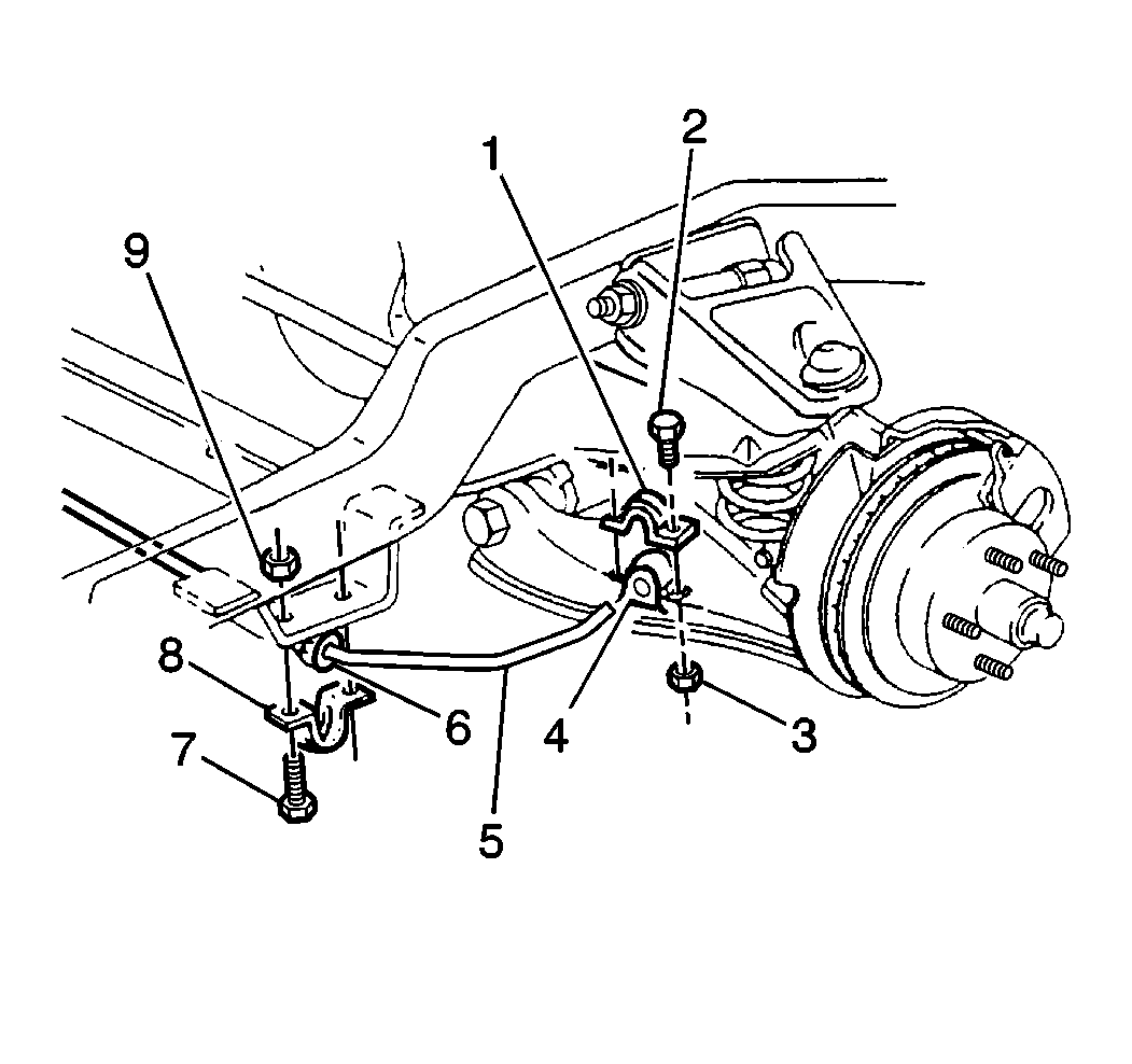
- Remove the front stabilizer shaft from the lower control arms.

- Remove the following components:
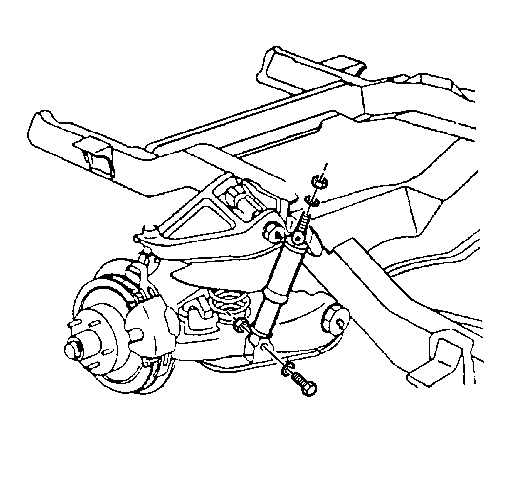
| • | Remove the shock absorbers from the lower control arms. |
Notice: Failure to disconnect the brake line clips from the suspension unit
will result in severe damage to the brake line when the unit is lowered from
the vehicle.
- Remove the brake line clip bolts from the front suspension crossmember.
- Remove the suspension crossmember from the engine mounts. Refer
to the following procedures:

- Remove the suspension
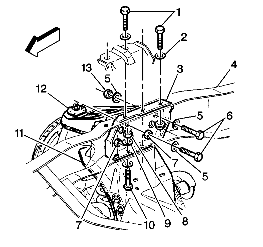
crossmember (11) from the frame rail (4).
| 15.1. | Raise the hoist in order to support the suspension crossmember.
Perform these steps before the suspension unit is lowered from the vehicle. |
| 15.2. | Support the engine. |
- Remove the upper control arm bracket from the following components:
| • | The frame side rail nuts (13) |
- Remove the following components:
| • | The suspension and crossmember unit bolts (10) |
| • | When removing the suspension and crossmember unit, lower
the suspension and crossmember unit in order to bring the unit clear
of the vehicle. |
Installation Procedure
For control arms and components, refer to
Lower Control Arm Replacement
or
Upper Control Arm Replacement
.
- Install the suspension and crossmember unit. Raise the unit with
the hoist and align the suspension crossmember and frame holes.

- Install the following
components:
| • | The suspension crossmember to frame rail bolts (10) |
Notice: Use the correct fastener in the correct location. Replacement fasteners
must be the correct part number for that application. Fasteners requiring
replacement or fasteners requiring the use of thread locking compound or sealant
are identified in the service procedure. Do not use paints, lubricants, or
corrosion inhibitors on fasteners or fastener joint surfaces unless specified.
These coatings affect fastener torque and joint clamping force and may damage
the fastener. Use the correct tightening sequence and specifications when
installing fasteners in order to avoid damage to parts and systems.
Important: The upper control arm to frame bracket bolts must be tightened first.
The crossmember must be in contact with the frame lower flange.
- Install the upper control arm to frame bracket to the following components:
Tighten
| • | For commercial models, tighten the bolts to 87 N·m
(64 lb ft). |
| • | For motorhome models, tighten the bolts to 135 N·m
(100 lb ft). |
- Install the crossmember to frame bolts (1) through the
reinforcement.
- Install the washers (2) and the nuts as used.
Tighten
| • | For commercial models, tighten the bolts to 87 N·m
(64 lb ft). |
| • | For motorhome models, tighten the bolts to 135 N·m
(100 lb ft). |
- Install the engine mount support bracket to suspension crossmember
bolts. Remove the engine support and lower the hoist. Refer to the following
procedures:
- Install the brake line clip to the crossmember.

- Install the shock absorber
to the lower control arm.
- Install the washers, the nuts, and the bolts.
Tighten
Tighten the nut to 102 N·m (75 lb ft).

- Install the stabilizer
shaft (5) to the lower control arm.
- Install the bracket (1), the bolts (2), and the
nuts (3).
Tighten
Tighten the nut to 33 N·m (24 lb ft).
- Connect the tie rod ends to the steering knuckle. Refer to
Tie Rod Replacement
in Steering Linkage.
- Connect the brake hose to the caliper. Refer to
Front Brake Hose Replacement
in Hydraulic Brakes.
- Install the brake hose clips to the upper control arms.
- Bleed the brake system. Refer to
Hydraulic Brake System Bleeding
in Hydraulic Brakes.
- Install the tire and wheel assembly. Refer to
Tire and Wheel Removal and Installation
in Tires and Wheels.
- Lower the vehicle.
- Connect the negative battery cable.
- Check the front wheel alignment. Refer to
Wheel Alignment Specifications
in Wheel Alignment.


