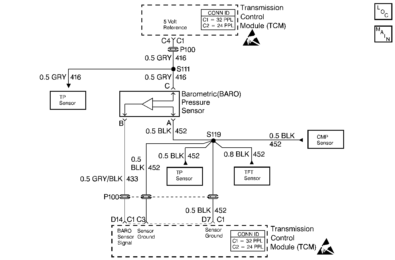
DTC 64 BARO Sensor Circuit Low L57 MFI

Circuit Description
The transmission control module (TCM) supplies 5 volts to the BARO sensor. As the atmospheric pressure changes the resistance within the BARO sensor also changes, modifying the voltage on the BARO sensor input signal. When atmospheric pressure is high, (100 kPa), input signal voltage is high (approx. 4.5 V). As atmospheric pressure decreases, so does the input signal voltage.
If the TCM detects a low voltage on the BARO sensor circuit, then DTC 64 sets.
Conditions for Running the DTC
| • | The ignition is ON. |
| • | System voltage is 12.0-16.0 volts. |
Conditions for Setting the DTC
BARO sensor signal voltage less than 1.9 volts for greater than 2 seconds.
Action Taken When the DTC Sets
| • | The TCM does not illuminate the malfunction indicator lamp (MIL). |
| • | No altitude compensation of shift patterns. |
| • | The TCM uses a default BARO value of 100 kPa. |
| • | The TCM stores DTC 64 in TCM history. |
Conditions for Clearing the DTC
| • | A scan tool clears the DTC from TCM history. |
| • | The TCM clears the DTC from TCM history if the vehicle completes 40 consecutive key cycles without a diagnostic fault occurring. |
| • | The TCM cancels the DTC default actions when the fault no longer exists and the ignition switch is OFF long enough in order to power down the TCM. |
Diagnostic Aids
| • | Inspect the wiring at the TCM, the transmission connector and all other circuit connecting points for the following conditions: |
| - | A backed out terminal |
| - | A damaged terminal |
| - | Reduced terminal tension |
| - | A chafed wire |
| - | A broken wire inside the insulation |
| - | Moisture intrusion |
| - | Corrosion |
| • | If the DTC does not set, use snapshot mode on the scan tool to trigger ON this DTC, then review data to identify source. |
Test Description
The numbers below refer to the step numbers on the diagnostic table.
-
This step verifies the 5 volt supply to the BARO sensor.
-
This step verifies a good BARO sensor ground circuit 452.
-
If the entire circuit is OK, the voltage measured will be approximately 5 volts.
Step | Action | Value(s) | Yes | No |
|---|---|---|---|---|
1 | Was the Powertrain On-Board Diagnostic (OBD) System Check performed? | -- | ||
Is the voltage within the specified values? | 4.7-5.3 v | |||
Using a test light connected to B+, probe ground circuit 452 (BLK) at the BARO sensor connector. Is test light ON? | -- | |||
Is the voltage greater than the specified value? | 4.7 volts | |||
5 | Verify proper terminal tension at the BARO sensor connector. Was the condition corrected? | -- | ||
6 | Replace the BARO sensor. Refer to BARO Sensor Replacement in Engine Controls. Is the replacement complete? | -- | -- | |
7 | Repair the open in the ground circuit 452 (BLK), from the BARO sensor to the TCM. Refer to Wiring Repairs in Wiring Systems. Is the repair complete? | -- | -- | |
8 | Repair the 5 volt reference circuit 416 to the BARO sensor. Refer to Wiring Repairs in Wiring Systems. Is the repair complete? | -- | -- | |
9 | Inspect circuit 433 for an open or a short to ground. Refer to General Electrical Diagnosis in Wiring Systems. Was a condition found? | -- | ||
10 | Replace the TCM. Refer to Powertrain Control Module Replacement/Programming in Engine Controls. Is the replacement complete? | -- | -- | |
11 | Repair the wiring as necessary. Refer to Wiring Repairs in Wiring Systems. Is the repair complete? | -- | -- | |
12 | Perform the following procedure in order to verify the repair:
Is the J 39200 DMM voltage within the specified value? | 1.9-4.9 volts | System OK |
