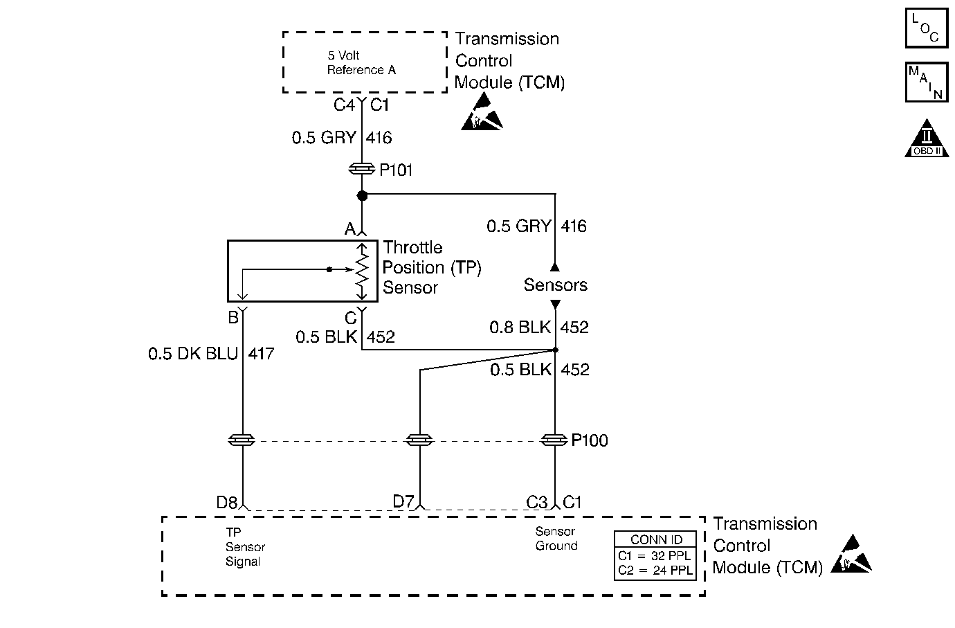
DTC 22 TP Sensor Circuit Low L57 MFI

Circuit Description
The throttle position (TP) sensor provides a voltage signal which changes relative to the throttle blade angle.
The TP sensor signal voltage varies from about 0.5 volt at idle, to about 5.0 volts at wide open throttle (WOT). The TP sensor signal is used by the TCM for most of the TCM control outputs.
Each time the voltage drops below 1.25 volts and stops, the TCM assumes this value as the 0 throttle angle. The TCM measures the percent throttle from this point on.
Conditions for Running the DTC
The engine is running.
Conditions for Setting the DTC
The TP sensor signal is less than 0.2 volts for greater than 1 second.
Action Taken When the DTC Sets
Important:: The scan tool does not indicate a default value.
| • | The TCM does not illuminate the MIL. |
| • | The TCM commands maximum line pressure. |
| • | The TCM uses 35% TP as a default. |
| • | The TCM inhibits 4th gear if in hot mode. |
| • | The TCM stores DTC 22 in TCM history. |
Conditions for Clearing the DTC
| • | A scan tool clears the DTC from TCM history. |
| • | The TCM clears the DTC from TCM history if the vehicle completes 40 consecutive key cycles without a diagnostic fault occurring. |
| • | The TCM cancels the DTC default actions when the fault no longer exists, and the ignition switch is OFF long enough in order to power down the TCM. |
Diagnostic Aids
The scan tool reads the throttle position in volts. The TP should read about 0.45 to 0.85 volt, with the throttle closed and the ignition switch turned ON, or at idle. The voltage should increase at a steady rate as the throttle is moved toward the wide open throttle (WOT).
An open or short to ground in the 5 volt reference circuit or the TP sensor signal circuit results in a DTC 22.
Scan the TP sensor while depressing the accelerator pedal with the engine stopped and the ignition ON. The display should vary from below 1.25 volts (1250 mV) when the throttle was closed, to over 4.5 volts (4500 mV) when the throttle is held at the wide open throttle (WOT) position.
Test Description
The numbers below refer to the step numbers on the diagnostic table.
-
If the TP signal measures less than 0.2 volt, then the fault exists.
-
This test simulates the DTC 21 (high voltage). If the TCM recognizes the high signal voltage, the TCM and the wiring harness are okay.
-
This test simulates a high signal voltage in order to check for an open in the TP signal circuit.
-
This step checks the 5 volt reference circuit for an open, short to ground, a poor connection, or a faulty TCM.
Step | Action | Value(s) | Yes | No |
|---|---|---|---|---|
1 | Was the On-Board Diagnostic (OBD) System Check performed? | -- | ||
Important:: Before clearing the DTCs, use the Scan Tool in order to record the Failure Records. Using the Clear Info function erases the Failure Records from the TCM. Does the Scan Tool display a TP signal less than the specified value? | 0.2 volts | |||
Does the Scan Tool display a TP signal greater than the specified value? | 4.0 volts | |||
Probe the TP sensor signal circuit 417 at harness terminal B with a test lamp connected to a 12 source (B+). Does the Scan Tool display a throttle position signal greater than the specified value? | 4.0 volts | |||
5 | The DTC is intermittent. If no additional DTCs are stored, refer to the Diagnostic Aids. If additional DTCs are stored, refer to those tables. Are any additional DTCs set? | -- | Go to the applicable DTC table | |
Check for an open in the 5 volt reference circuit 416 (GRY). Refer to General Electrical Diagnosis in Wiring Systems. Was an open condition found? | -- | |||
7 | Check the 5 volt reference circuit 416 for a short to the ground. Refer to General Electrical Diagnosis in Wiring Systems. Was a short to ground condition found? | -- | ||
8 | Check the TP sensor signal circuit 417 (DK BLU) for an open. Refer to General Electrical Diagnosis in Wiring Systems. Was an open condition found? | -- | ||
9 | Check the TP sensor signal circuit 417 for a short to the ground. Refer to General Electrical Diagnosis in Wiring Systems. Was a short to ground condition found? | -- | ||
10 | Check for a faulty connection at the TCM. Was a condition found? | -- | ||
11 | Repair the circuit as necessary. Refer to Wiring Repairs in Wiring Systems. Is the repair complete? | -- | -- | |
12 | Replace the faulty TP sensor. Refer to Throttle Position Sensor Replacement in Engine Controls. Is the replacement complete? | -- | -- | |
13 |
Important:: If the TCM is faulty, re-use the PROM (Mem-cal). Refer to Powertrain Control Module Replacement/Programming in Engine Controls. Replace the TCM. Is the replacement complete? | -- | -- | |
14 | Perform the following procedure in order to verify the repair:
Is the Scan Tool TP sensor voltage greater than the specified value? | 0.2 volts | System OK |
