DTC 75 System Voltage Low L57 MFI

Circuit Description
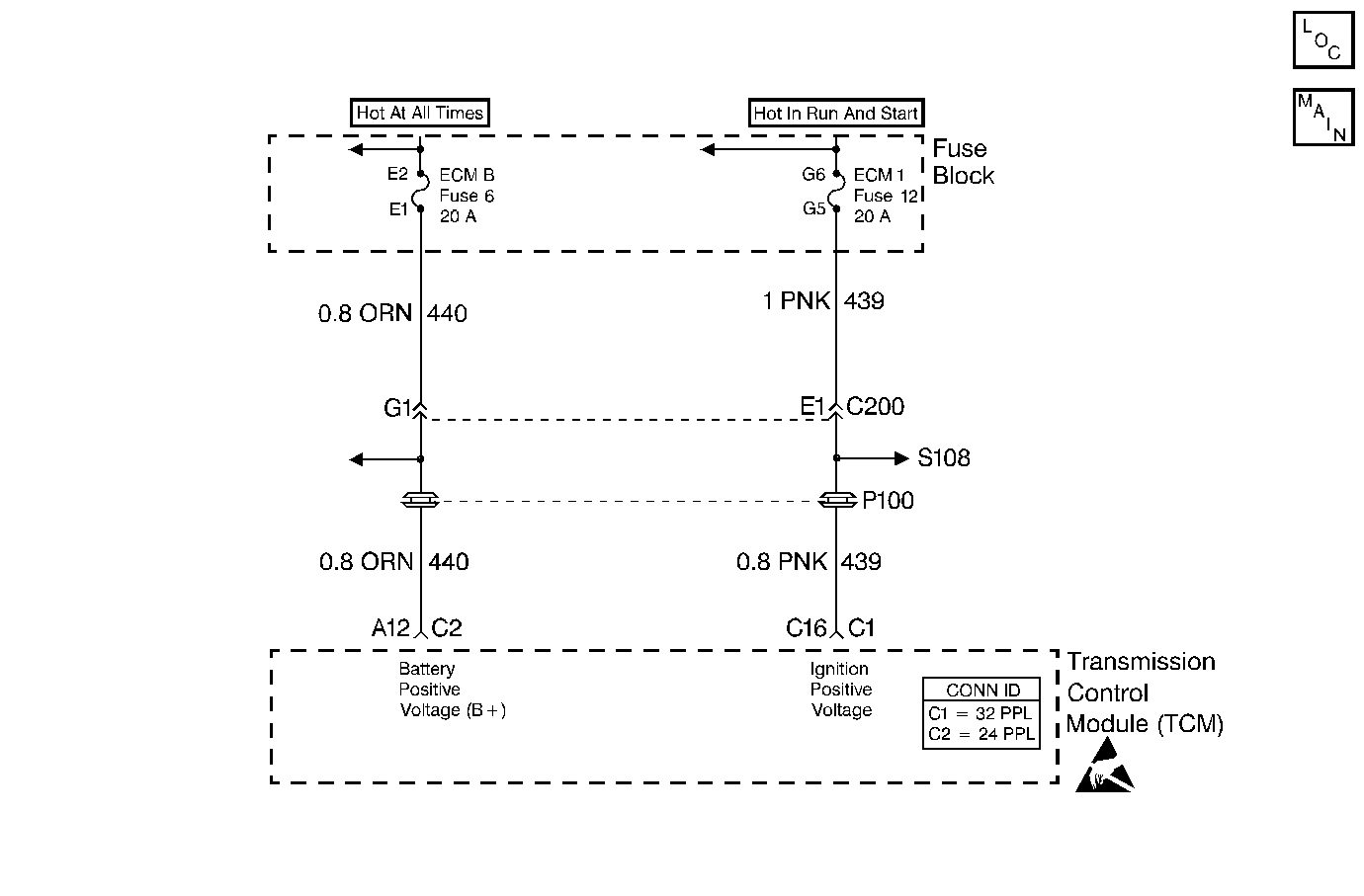
The ignition voltage is supplied to the transmission control module (TCM) to indicate the status of the ignition switch. Battery voltage is supplied to the TCM on circuit 440 to maintain memory of learned functions and parameters.
If the TCM detects low voltage input, then DTC 75 sets.
Conditions for Running the DTC
| • | The ignition is ON. |
| • | The engine speed is greater than 300 RPM. |
Conditions for Setting the DTC
System voltage is:
| • | Less than 7.3 volts at -40°C (-40°F) or |
| • | Less than 10.3 volts at 90°C (194°F) or |
| • | Less than 11.7 volts at 150°C (304°F) |
| • | The above conditions are met for 4 seconds. |
Action Taken When the DTC Sets
| • | The TCM does not illuminate the malfunction indicator lamp (MIL). |
| • | The PC solenoid valve is turned OFF. |
| • | Soft landing to default 2nd gear. |
| • | Inhibit fourth gear and TCC. |
| • | The TCM stores DTC 75 in TCM history. |
Conditions for Clearing the DTC
| • | A scan tool clears the DTC from TCM history. |
| • | The TCM clears the DTC from TCM history if the vehicle completes 40 consecutive key cycles without a diagnostic fault occurring. |
| • | The TCM cancels the DTC default actions when the fault no longer exists and the ignition switch is OFF long enough in order to power down the TCM. |
Diagnostic Aids
| • | Inspect the wiring at the TCM, the transmission connector and all other circuit connecting points for the following conditions: |
| - | A backed out terminal |
| - | A damaged terminal |
| - | Reduced terminal tension |
| - | A chafed wire |
| - | A broken wire inside the insulation |
| - | Moisture intrusion |
| - | Corrosion |
| • | Charging the battery with a battery charger and jumpstarting an engine may set DTCs. |
| • | If this DTC is set when an accessory is operated, inspect for faulty connections or an excessive current draw. |
| • | Inspect for faulty electrical connections at the starter solenoid. |
| • | Inspect for faulty electrical connections at the fusible link. |
| • | Inspect for loose or damaged terminals at the generator. |
| • | Inspect the generator belt wear condition and tension. |
Test Description
The numbers below refer to the step numbers on the diagnostic table.
-
This step tests the charging system voltage.
-
This step tests the battery voltage input at the TCM.
-
This step tests the ignition voltage inputs at the TCM.
Step | Action | Value(s) | Yes | No | ||||
|---|---|---|---|---|---|---|---|---|
1 | Was the Powertrain On-Board Diagnostic (OBD) System Check performed? | -- | ||||||
2 |
Important:: Before clearing the DTCs, use the scan tool in order to record the Failure Records. Using the Clear Info function erases the Failure Records from the TCM. Is the voltage higher than the specified value? | 10.5 volts | Go to Charging System Check | |||||
Is the J 39200 DMM battery voltage within the specified value? | 13-15.5 volts | Go to Charging System Check | ||||||
4 |
Is the Scan Tool voltage within 0.5 volts of the J 39200 DMM voltage? | -- | Go to Diagnostic Aids | |||||
Is the J 39200 DMM voltage within 0.5 volts of the battery voltage reading from Step 3? | -- | |||||||
6 | Repair the high resistance condition in circuit 440 (ORN). Refer to Wiring Repairs in Wiring Systems. Is the repair complete? | -- | -- | |||||
Is the J 39200 DMM voltage within 0.5 volts of battery voltage from Step 3? | -- | |||||||
8 | Repair the high resistance condition in circuit 439 (PNK). Refer to Wiring Repairs in Wiring Systems. Is the repair complete? | -- | -- | |||||
9 | Replace the TCM. Refer to Powertrain Control Module Replacement/Programming in Engine Controls. Is the replacement complete? | -- | -- | |||||
10 | Perform the following procedure in order to verify the repair:
Is the Scan Tool ignition voltage within the specified value? | 12.0-16.0 volts | System OK |
