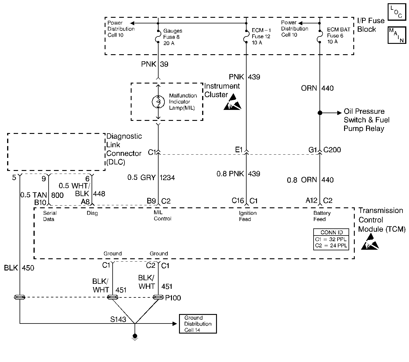
Malfunction Indicator Lamp (MIL) Inoperative L57 MFI

Circuit Description
There should always be a steady malfunction indicator lamp (MIL) with the ignition on RUN and engine OFF. Switched battery voltage is supplied to the lamp. The TCM controls the lamp and turns it ON by providing a ground path through circuit 1234.
Diagnostic Aids
| • | If the gauge fuse is open, this results in no brake warning light, oil light, generator light, seat belt reminder, etc. |
| • | Inspect the wiring for faulty electrical connections at the TCM. Inspect the wiring for faulty electrical connections at the instrument cluster connector. Look for the following conditions: |
| - | A backed out terminal |
| - | A damaged terminal |
| - | Reduced terminal tension |
| - | A chafed wire |
| - | A broken wire inside the insulation |
| - | Moisture intrusion |
| - | Corrosion |
| • | When diagnosing for an intermittent short or open, massage the wiring harness while watching the test equipment for a change. |
Test Description
The numbers below refer to the step numbers on the diagnostic table.
-
This step isolates the fault to the wiring circuit or the TCM and its connections.
-
This step inspects for a short to ground that causes the fuse to open.
-
This step checks for an open from the fuse to the MIL bulb.
-
This step checks for an open or short to power from the bulb to the TCM connector.
-
This step checks for an open condition with the instrument panel printed circuit.
Step | Action | Value(s) | Yes | No |
|---|---|---|---|---|
1 | Was the On-Board Diagnostic System Check performed? | -- | ||
Is the MIL ON? | -- | |||
Inspect the gauge fuse for an open. Refer to General Electrical Diagnosis in Wiring Systems. Was an open condition found? | -- | |||
4 | Inspect circuit 39 (PNK) for a short to ground. Refer to General Electrical Diagnosis in Wiring Systems. Was a condition found? | -- | Go to Diagnostic Aids | |
5 | Repair the short to ground condition. Refer to Wiring Repairs in Wiring Systems. Is the repair complete? | -- | -- | |
6 | Inspect the MIL bulb. Refer to General Electrical Diagnosis in Wiring Systems. Was a condition found? | -- | ||
7 | Replace the MIL bulb. Is the MIL illuminated? | -- | -- | |
Inspect circuit 39 (PNK) for an open. Refer to General Electrical Diagnosis in Wiring Systems. Was an open condition found? | -- | |||
Inspect circuit 1234 (GRY) for an open or short to power. Refer to General Electrical Diagnosis in Wiring Systems. Was a condition found? | -- | |||
Inspect for an open in the instrument cluster circuit of the MIL. Refer to General Electrical Diagnosis in Wiring Systems. Was a condition found? | -- | -- | ||
11 | Repair the open or short to power condition. Refer to Wiring Repairs in Wiring Systems. Is the repair complete? | -- | -- | |
12 | Repair the open condition. Refer to Wiring Repairs in Wiring Systems. Is the repair complete? | -- | -- | |
13 | Inspect the TCM connector pins and terminals for corrosion, reduced terminal tension or a faulty TCM ground. Was a condition found? | -- | ||
14 | Repair the faulty circuit or terminal connection. Refer to Wiring Repairs in Wiring Systems. Is the repair complete? | -- | -- | |
15 | Inspect circuit 440 (ORN) and circuit 439 (PNK) for voltage at the TCM connector. Refer to General Electrical Diagnosis in Wiring Systems. Is the voltage within the specified range? | 13.0-15.0 volts | ||
16 | Repair the wiring as necessary. Refer to Wiring Repairs in Wiring Systems. Is the repair complete? | -- | -- | |
17 | Replace the TCM. Refer to Powertrain Control Module Replacement/Programming in Engine Controls. Is the replacement complete? | -- | -- |
