Front Coil Springs Replacement Independent
Removal Procedure
For lower control arm and components, refer to
Lower Control Arm and Components (Independent Suspension)
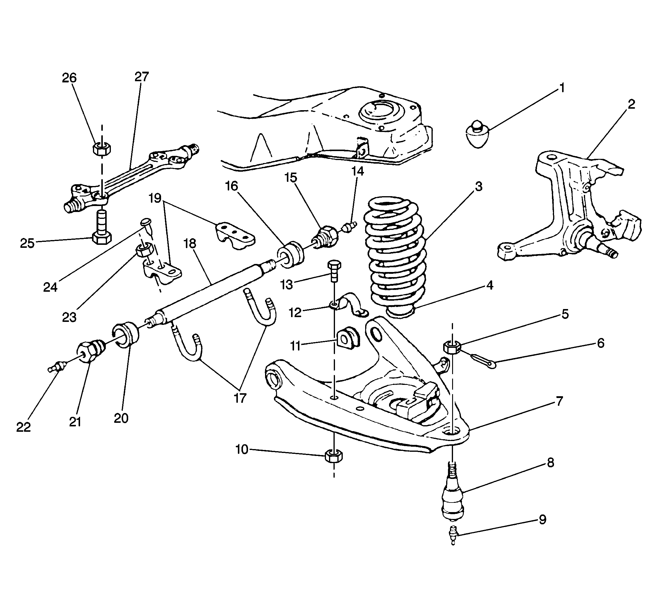
Tools Required
- Raise the vehicle. Support the vehicle with suitable safety stands,
allowing the control arms to hang free.
- Remove the tire and wheel assembly. Refer to
Tire and Wheel Removal and Installation
in Tires
and Wheels.
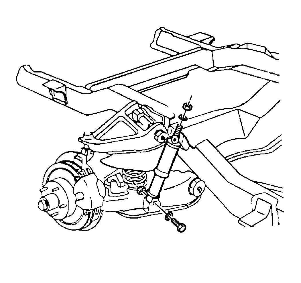
- Disconnect the lower end
of the shock absorber and move the shock aside.
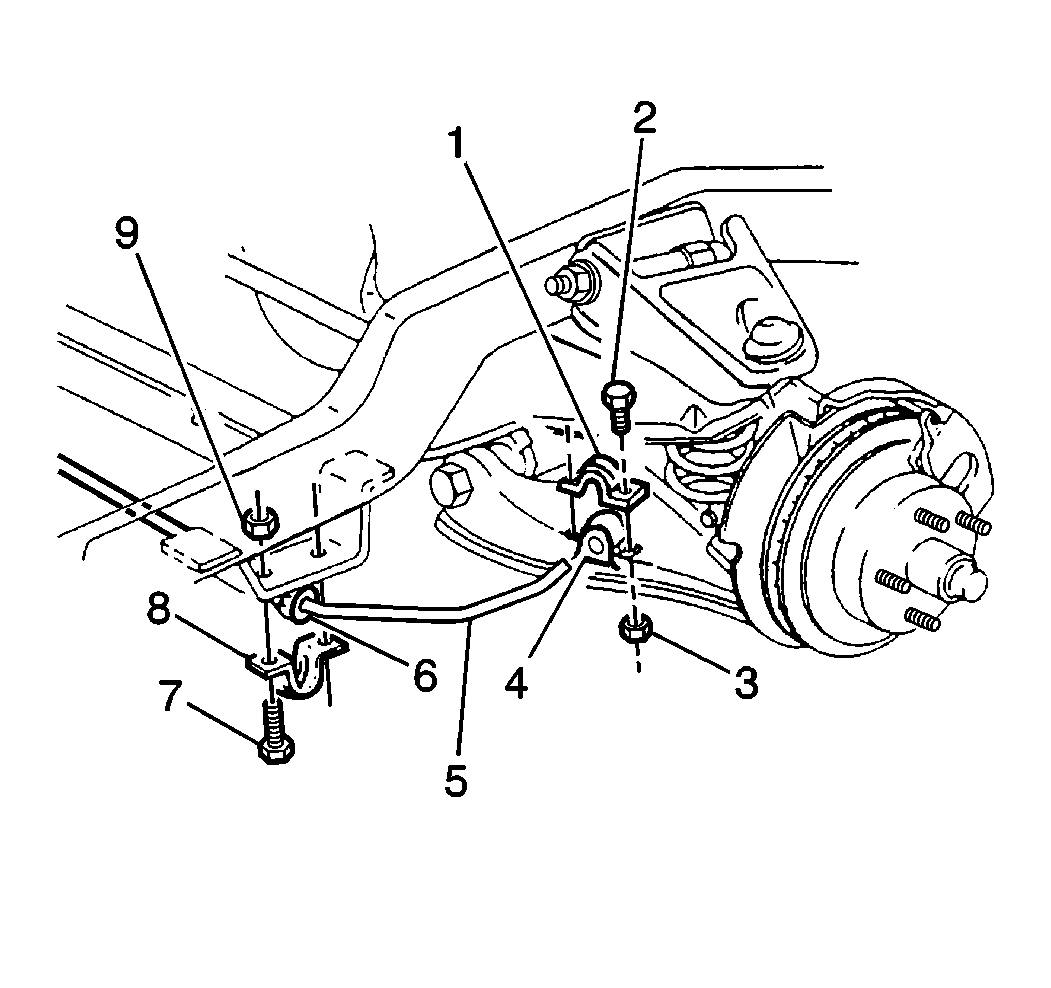
- Remove the nuts (3), the
bolts (2), the bracket (1), and the stabilizer shaft (5) from the lower control
arm.
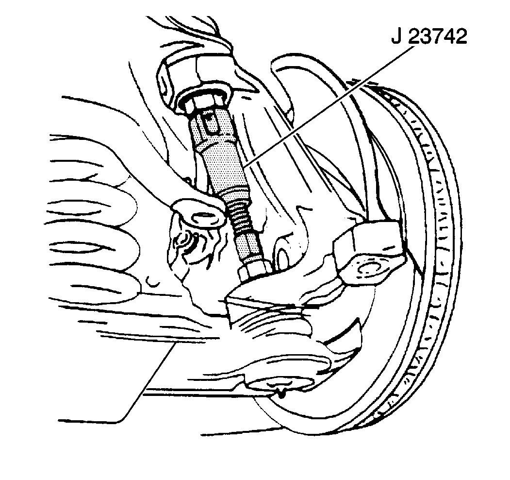
- Remove the nut from the
lower ball joint.
- Disconnect the lower ball joint from the steering knuckle.
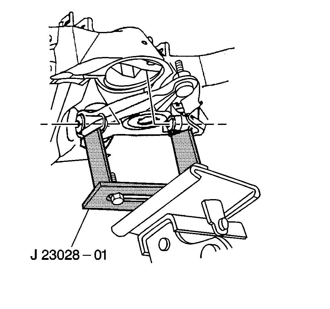
Caution: Tool J 23028-01 should be secured to a suitable jack
or personal injury could result.
Important: As a safety precaution, install a chain around the coil spring and through
the lower control arm.
- In order to install a chain with an air cylinder installed, use the
following procedure:
- Remove the valve core from the cylinder.
- Expel the air by pushing on the cylinder with a pry bar.
- Replace the valve cap in order to retain vacuum.
- Push the air cylinder as far as possible toward the top of the
spring.
- Raise the jack in order to relieve the tension from the lower
control arm pivot shaft.
Remove the U-bolts or bolts and the nuts.
- Lower the control arm by slowly releasing the jack until the spring
can be removed.
- Do not apply too much force on the ball joint. This can damage
the ball joint.
- Install the J 23028-A
on a suitable jack and then place under the lower control arm.
- When compression is relieved from the spring, remove the spring
and the safety chain. Proper maneuvering of the spring will allow for easy
removal.
- Remove the air cylinder, if equipped. Inspect the air cylinder
for leaks using the following procedure:
| 17.1. | Replace the valve core. |
| 17.2. | Inflate the air cylinder to 138 kPa (20 psi). |
| 17.3. | Submerge the cylinder in water. |
| 17.4. | Check for air bubbles. |
Installation Procedure
For lower control arm and components, refer to
Lower Control Arm and Components (Independent Suspension)

- Install the air cylinder, if equipped. Install the air cylinder
inside of the coil spring so that the Schrader valve protrudes through the
hole in the lower control arm.
Caution: Tool J 23028-01 should be secured to a suitable jack
or personal injury could result.
Important: Install a chain around the coil spring and through the lower control
arm as an additional safety precaution.
- Place the coil spring into position on the lower control arm.
| • | Place the end of the coil spring at the drain hole in the lower
control arm. |
- Slowly lift the lower control arm into position.
| • | Line up the front indexing hole in the shaft with the crossmember
attaching studs. |
| • | Do not damage the lower ball joint. |
Notice: Use the correct fastener in the correct location. Replacement fasteners
must be the correct part number for that application. Fasteners requiring
replacement or fasteners requiring the use of thread locking compound or sealant
are identified in the service procedure. Do not use paints, lubricants, or
corrosion inhibitors on fasteners or fastener joint surfaces unless specified.
These coatings affect fastener torque and joint clamping force and may damage
the fastener. Use the correct tightening sequence and specifications when
installing fasteners in order to avoid damage to parts and systems.
- Install the U-bolts
or bolts and the nuts.
Tighten
Tighten the nuts to 115 N·m (85 lb ft).
- Lower the floor jack and remove the J 23028-A
.

- Install the stabilizer
shaft (5), the bracket (1), the bolts (2), and the nuts (3) to the lower
control arm.
Tighten
Tighten the nuts to 33 N·m (24 lb ft).

- Install the shock absorber
to the lower control arm.
- Install the washer, the bolt, and the nut.
Tighten
Tighten the nuts to 80 N·m (59 lb ft).
- Install the tire and wheel assembly. Refer to
Tire and Wheel Removal and Installation
in Tires
and Wheels.
- Inflate the air cylinders, if equipped, to 414 kPa (60 psi).
| • | Maintain the inflation pressure at 69 kPa (10 psi)
in order to avoid chafing. |
| • | Under load, adjust the air cylinder air bags to the following
pressures: |
| - | For a 4,300, 4,500, and 5,000 lb capacity front suspension,
inflate the air bags to 276-414 kPa (40-60 psi). |
| - | For a 5,300 lb capacity front suspension, inflate the air
bags to 414-552 kPa (60-80 psi). |
| - | For a 5,500 lb capacity front suspension, inflate the air
bags to 552-689 kPa (80-100 psi). |
- Lower the vehicle.
- Check the front wheel alignment. Refer to
Wheel Alignment Specifications
in Wheel
Alignment.


