Lower Control Arm Ball Joint Replacement Independent
Inspection Procedure
- Raise the vehicle.
- Remove the tire and wheel assembly. Refer to
Tire and Wheel Removal and Installation
in Tires
and Wheels.
- Support the weight of the control arms at the wheel hub and drum.

- Measure the distance between
the tip of the ball joint stud and the tip of the grease fitting below the
ball joint.
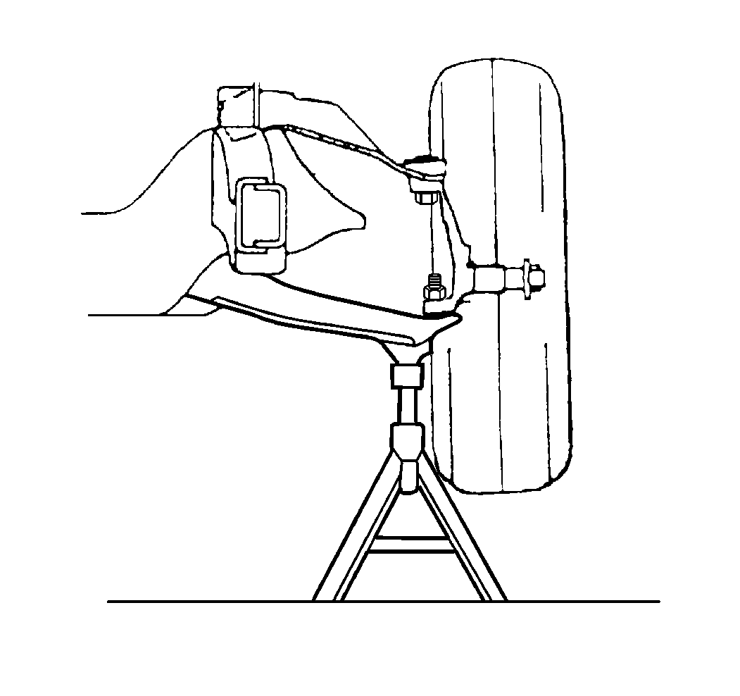
- Move the support to underneath
the control arm, allowing the wheel hub and drum to hang free.

- Measure the distance again
as in Step 4. If the difference in measurements exceed 2.38 mm (3/32 in),
this indicates that the ball joint is worn. The ball joint MUST be replaced.
- If the ball joint seals are cracked, cut, or torn, replace the
ball joint.
Removal Procedure
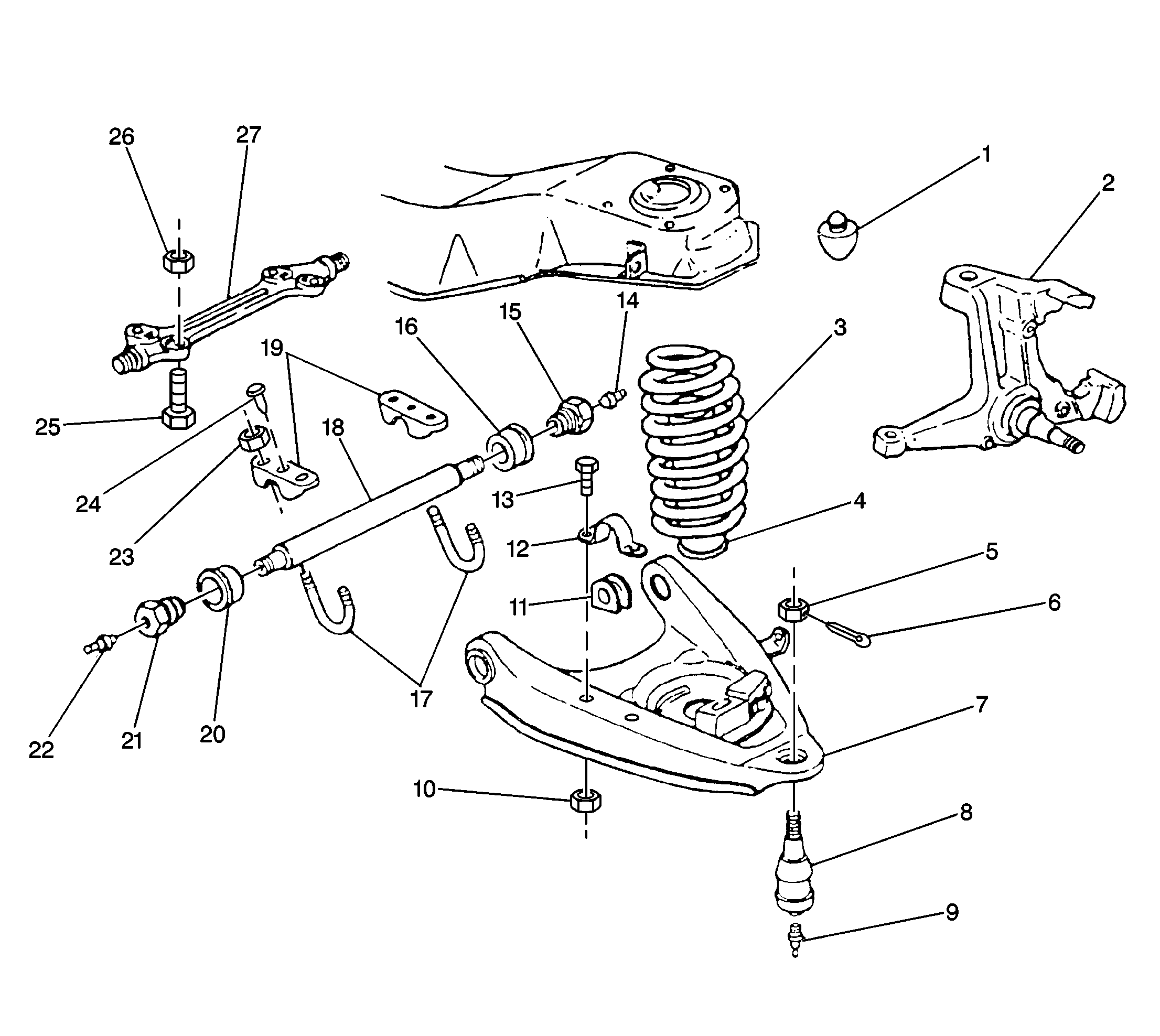
For lower control arm and components, refer to
Lower Control Arm and Components (Independent Suspension)
Tools Required
| • | J 9519-E Ball
Joint Remover and Installer Set |

- Raise the vehicle on a
hoist. If a frame hoist is used, support the lower control arm with a floor
stand.
- Remove the tire and wheel assembly. Refer to
Tire and Wheel Removal and Installation
in Tires
and Wheels.
- Remove the cotter pin, the nut, and the grease fitting. Loosen
the nut two turns, but do not remove.
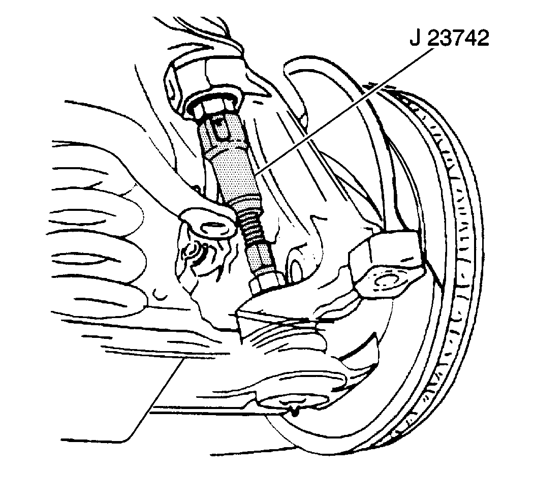
- Loosen the ball joint
in the steering knuckle.
| 4.1. | Use the J 23742
between
the ball joint studs. |
| 4.2. | You may need to remove the caliper and wire the caliper to the
frame in order to gain clearance for the J 23742
. Refer to
Brake Caliper Replacement
in Disc Brakes. |
| 4.3. | Extend the J 23742
until the lower ball joint breaks free from the steering knuckle. |
| 4.4. | Remove the nut and the J 23742
. |
- Take the hub/rotor and
the knuckle assembly off of the lower ball joint.
Caution: Floor jack must remain under the lower control arm during
removal and installation to retain the lower control arm in position. Failure
to do so could result in personal injury.
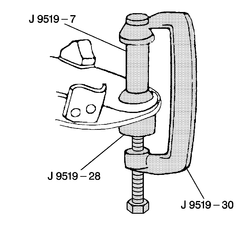
- Remove the ball joint from the lower control arm.
| 6.1. | Install the tools as shown. |
| 6.2. | Turn the hex head screw until the ball joint comes free from the
lower control arm. |
| 6.3. | Remove the tools and the ball joint. |
Installation Procedure
For lower control arm and components, refer to
Lower Control Arm and Components (Independent Suspension)

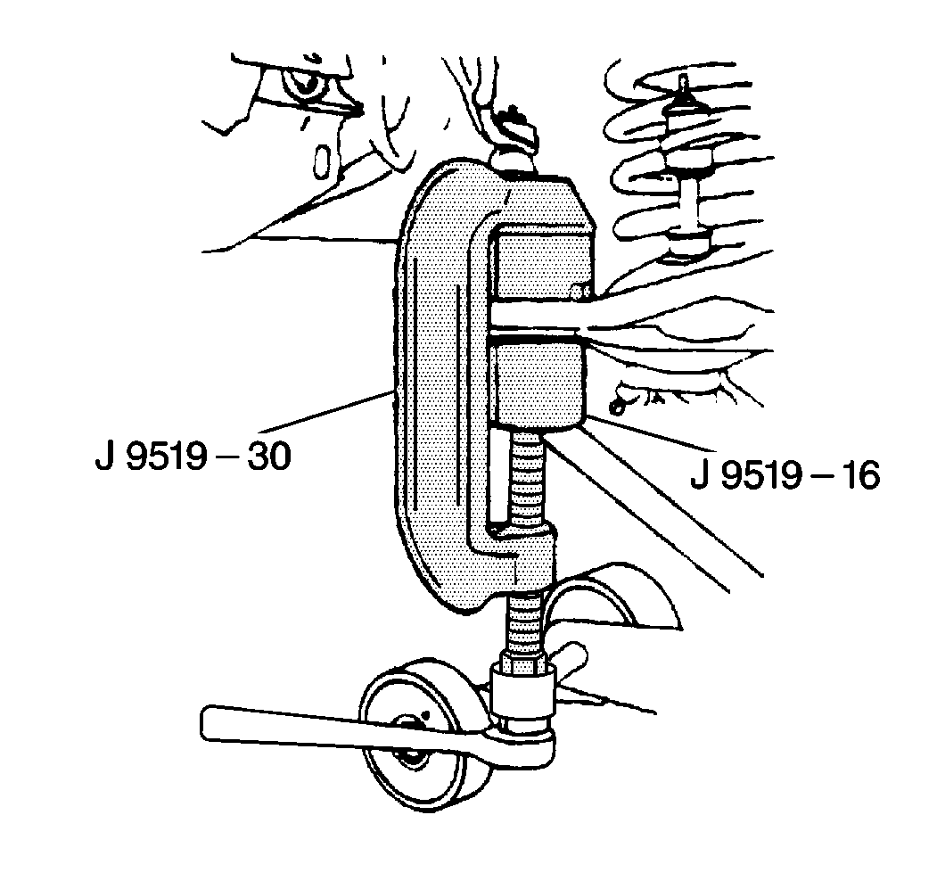
- Install the ball joint
into the lower control arm.
| 1.1. | Start the ball joint into the control arm and install the tools
as shown. |
| 1.2. | Position the bleed vent in the rubber boot, facing inward. |
| 1.3. | Turn the hex head screw until the ball joint is seated in the
lower control arm. |
- Install the ball joint into the steering knuckle. Mate the steering
knuckle to the lower ball joint.
- Install the caliper, if removed. Refer to
Brake Caliper Replacement
in Disc Brakes.
Notice: Use the correct fastener in the correct location. Replacement fasteners
must be the correct part number for that application. Fasteners requiring
replacement or fasteners requiring the use of thread locking compound or sealant
are identified in the service procedure. Do not use paints, lubricants, or
corrosion inhibitors on fasteners or fastener joint surfaces unless specified.
These coatings affect fastener torque and joint clamping force and may damage
the fastener. Use the correct tightening sequence and specifications when
installing fasteners in order to avoid damage to parts and systems.
- Install the lower
ball joint nut.
Tighten
Tighten the nut to 122 N·m (90 lb ft).
Important: Maximum torque to align the cotter pin is 175 N·m (130 lb ft).
- Install the cotter pin.
- Install the grease fitting. Lubricate the ball joint with the
recommended lubricant until visible. Refer to
Fluid and Lubricant Recommendations
in Maintenance and Lubrication.
- Install the tire and wheel assembly. Refer to
Tire and Wheel Removal and Installation
in Tires
and Wheels.
- Lower the vehicle.
- Check the front wheel alignment. Refer to
Wheel Alignment Specifications
in Wheel
Alignment.


