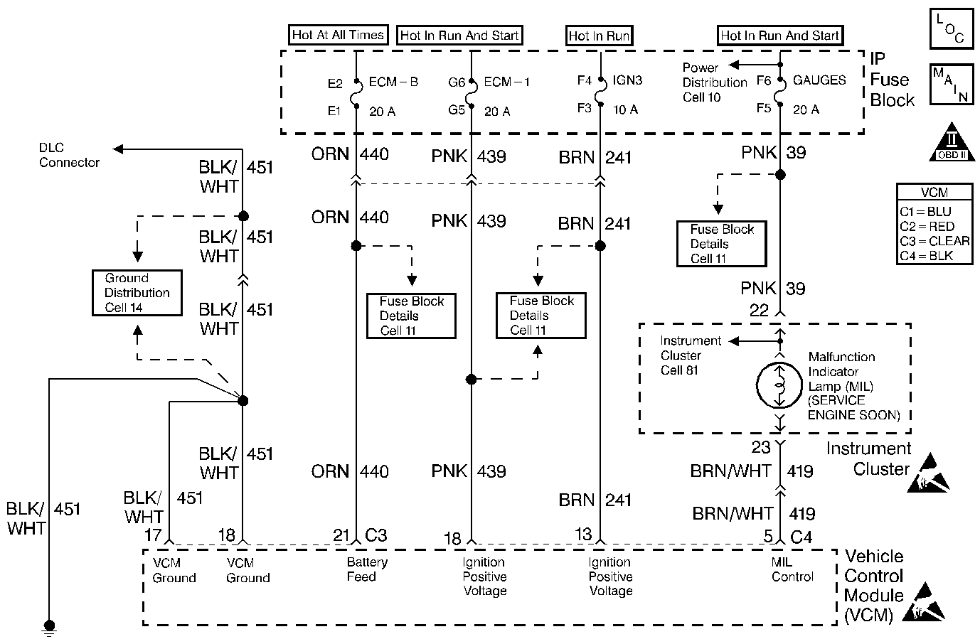
Circuit Description
When the ignition switch is initially turned to the run position, the malfunction indicator lamp (MIL) will be ON steady. When the engine is running and there are no active type A or B DTCs stored, refer to Diagnostic Trouble Code (DTC) List (Definitions) , the Vehicle Control Module (VCM) turns OFF the MIL. The ignition switch supplies battery voltage directly to the MIL through the gauge fuse. The VCM controls the MIL by providing a ground path through the MIL control circuit in order to turn ON the MIL.
Diagnostic Aids
An open gauge fuse will cause the entire IP cluster to be inoperative.
An intermittent may be caused by any of the following conditions:
| • | A poor connection |
| • | Rubbed through wire insulation |
| • | A broken wire inside the insulation |
Thoroughly check any circuitry that is suspected of causing the intermittent complaint. Refer to Intermittents and Poor Connections Diagnosis in Wiring Systems.
If a repair is necessary, refer to Wiring Repairs or Connector Repairs in Wiring Systems.
Test Description
The numbers below refer to step numbers on the diagnostic table.
-
A MIL that responds correctly to the scan tool command indicates that the condition is not present at this time.
-
The MIL should be OFF. This step checks for a short to ground in the MIL control circuit by removing the VCM from the circuit.
-
This step checks the MIL control circuit for a short to B+ or a problem with the VCM.
-
Locate and repair any shorts that may have caused the fuse to open BEFORE replacing the fuse.
Step | Action | Values | Yes | No |
|---|---|---|---|---|
1 | Did you perform the Powertrain On-Board Diagnostic (OBD) System Check? | -- | ||
2 |
Is the MIL ON? | -- | ||
Command the MIL OFF and ON using a scan tool. Does the MIL turn OFF and ON when commanded? | -- | Go to Diagnostic Aids | ||
Is the MIL OFF? | -- | |||
5 | Check for an open in the Gauge, the Battery Positive voltage or the Ignition Positive voltage fuses. Are any of the fuses open? | -- | ||
Is the MIL ON? | -- | |||
7 | Is the fuse in the fused jumper open? | -- | ||
8 | Check for an open in the MIL control circuit. Repair as necessary. Refer to Wiring Repairs in Wiring Systems. Did you find a problem? | -- | ||
9 | Check for an open between the MIL and the Gauge fuse. Repair as necessary. Refer to Wiring Repairs in Wiring Systems. Did you find a problem? | -- | ||
10 | Check for an open MIL. Repair as necessary. Refer to Wiring Repairs in Wiring Systems. Did you find a problem? | -- | ||
11 | Check the Instrument Panel (IP) cluster harness connections. Repair as necessary. Refer to Connector Repairs in Wiring Systems. Did you find a problem? | -- | ||
12 | Replace the Instrument Panel (IP) cluster. Refer to IP Cluster Replacement in Instrument Panel, Gauges and Console. Is the action complete? | -- | -- | |
13 | Repair the short to ground in the MIL control circuit. Refer to Wiring Repairs in Wiring Systems. Is the action complete? | -- | -- | |
Is the action complete? | -- | -- | ||
15 | Repair the short to voltage in the MIL control circuit between the VCM and the MIL lamp. Refer to Wiring Repairs in Wiring Systems. Is the action complete? | -- | -- | |
16 |
Does the test lamp light on all circuits tested? | -- | ||
17 | Probe both of the VCM ground circuits at the VCM connector with a test lamp connected to B+ Does the test lamp light on both circuits? | -- | ||
18 | Repair the open in the circuit. Refer to Wiring Repairs in Wiring Systems. Did you find a problem? | -- | ||
19 | Repair the open in the VCM ground circuit. Refer to Wiring Repairs in Wiring Systems. Is the action complete? | -- | -- | |
20 | Check for a poor connection at the VCM. Repair as necessary. Refer to Connector Repairs in Wiring Systems. Did you find a problem? | -- | ||
21 |
Important:: Program the replacement PCM. Refer to VCM Replacement/Programming . Replace the PCM. Is the action complete? | -- | -- | |
22 |
Is the MIL ON? | -- | ||
23 | Command the MIL OFF and ON using a scan tool. Does the MIL turn OFF and ON when commanded? | -- | System OK | Go to Step 2 |
