For 1990-2009 cars only
Removal Procedure
Tools Required
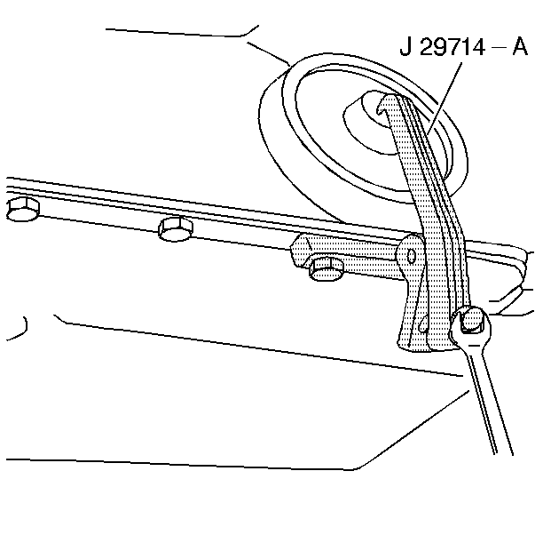
J 29714-A Servo Cover Depressor
- Raise the vehicle. Support the vehicle with safety stands. Refer to General Vehicle Lifting and Jacking in General Information.
- Lower the transmission if needed for clearance. Refer to Transmission Replacement .
- Install the J 29714-A
- Tighten the bolt in order to compress the servo cover.
- Remove the servo cover retaining ring.
- Remove the J 29714-A .
- Remove the servo cover and the O-ring seal. If the servo cover seems to be hung up on the seal, cut and remove the O-ring seal before removing the cover.
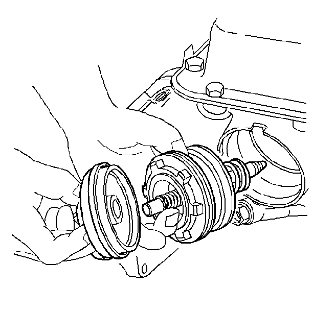
- Remove the 2-4 servo assembly.
- Disassemble the 2-4 servo assembly. Refer to 2-4 Servo Disassemble and 2-4 Band Servo Piston Pin Length Check .


Installation Procedure
Tools Required
J 29714-A Servo Cover Compressor
- Assemble the 2-4 servo assembly. Refer to 2-4 Servo Assembly Installation .
- Install the 2-4 servo assembly into the 2-4 servo bore.
- Install the J 29714-A
- Tighten the bolt in order to compress the servo cover.
- Install the servo cover retaining ring.
- Remove the J 29714-A from the oil pan flange.
- Install the oil pan bolt.
- Remove the safety stands.
- Lower the vehicle.
- Check the automatic transmission fluid level and add new automatic transmission fluid as needed. Refer to Transmission Fluid Check and to Fluid Capacity .


Tighten
Tighten the oil pan bolt to 11 N·m (97 lb in).
Notice: Use the correct fastener in the correct location. Replacement fasteners must be the correct part number for that application. Fasteners requiring replacement or fasteners requiring the use of thread locking compound or sealant are identified in the service procedure. Do not use paints, lubricants, or corrosion inhibitors on fasteners or fastener joint surfaces unless specified. These coatings affect fastener torque and joint clamping force and may damage the fastener. Use the correct tightening sequence and specifications when installing fasteners in order to avoid damage to parts and systems.
