NEW PRODUCT ANNOUNCEMENT HYDRA-MATIC 4L60-E

SUBJECT: NEW PRODUCT ANNOUNCEMENT HYDRA-MATIC 4L60-E AUTOMATIC TRANSMISSION - SERVICE REPLACEMENT TRANSMISSION ASSEMBLY (SRTA)
MODEL and YEAR: 1993 C/K, S/T, M/L TRUCKS AND G VANS
TRANSMISSION APPLICATIONS:
1993 HYDRA-MATIC 4L60-E
TRANSMISSION MODELS:
All
SUBJECT: ------- New Product Announcement HYDRA-MATIC 4L60-E
VEHICLE APPLICATIONS:
C/K - Trucks under 8600 GVW S/T - Trucks with 4.3L Non Turbo M/L and G - Vans
BULLETIN COVERS
This bulletin covers the HYDRA-MATIC 4L60-E Service Replacement Transmission Assembly (SRTA) Program and limited on-car repair guidelines. SRTA models and service parts can be ordered from your local General Motors Service Parts Operations (GMSPO) Parts Distribution Center.
The HYDRA-MATIC 4L60-E is a new transmission model that has electronic shift controls to control shift points.
SRTA ADVANTAGES
A SRTA is the product of a highly successful, customer satisfaction driven program that parallels the existing HYDRA-MATIC 3T40, HYDRA-MATIC 4T60 and HYDRA-MATIC 4L60 programs.
GMSPO Parts Distribution Centers are committed to 48 hour maximum delivery time for all SRTA models, with no VIP charges.
GENERAL GUIDELINES
On-Car Service or SRTA:
All service parts will be available so that bench repairs can be performed January 01, 1993 (providing the technician has taken the HYDRA-MATIC 4L60-E one-day training class number 17001.18). Until then, limited on-car repairs or SRTA will be the only service options available.
Dealer HYDRA-MATIC 4L60-E transmission repairs include:
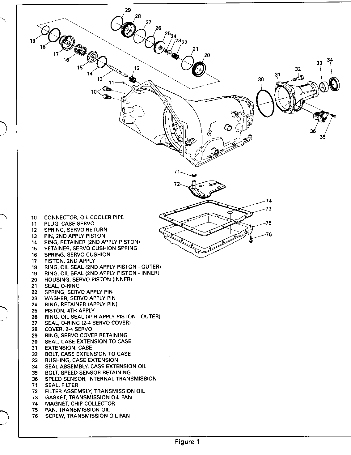
Limited on-vehicle serviceable items. Reference Figure 1.
Parts needed to perform limited on-vehicle service on a HYDRA-MATIC 4L60-E transmission are currently available through your local Parts Distribution Center (PDC).
Transmission conditions considered for SRTA usage:
All repairs that cannot be corrected by replacement of the parts are shown in Figure 1.
IMPORTANT
Do not attempt repairs on a HYDRA-MATIC 4L60-E, unless the part is shown in Figure 1 and listed in the repair parts list in this bulletin. All returned HYDRA-MATIC 4L60-E transmissions will be disassembled and inspected in an effort to increase product integrity Attempting repairs could destroy root cause analysis data.
COOLER FLUSHING
Cooler flushing and a flow check MUST be performed whenever a transmission is removed for service. It is essential to flush the cooler after SRTA installation, major overhaul, in the case of pump or torque converter replacement, or when fluid contamination is suspected. Use Kent-Moore tool J35944 and solvent J35944-20 to flush the cooler. Instructions are published in each service manual On-vehicle Service Section.
SERVICE PARTS INFORMATION
HYDRA-MATIC 4L60-E SRTA MODEL REPLACEMENT CHART
SRTA Part Model Description --------- ----- ----------- 8685955 3CBD 4.3L LB4 C&G Truck 8685956 3CFD 5.OL L03 C Truck 8685957 3CJD 5.7L L05 C&G Truck 8685958 3CLD 6.2L Diesel C&G Truck 8685959 3KAD 4.3L LB4 K Truck 8685960 3KBD 5.OL L03 K Truck 8685961 3KCD 5.7L L05 K Truck 8685962 3KDD 6.2L Diesel K Truck 8685963 3MJD 4.3L LB4 M Truck 8685964 3MDD 4.3L L35 L Truck 8685965 3MND 4.3L LB4 L Truck 8685966 3MSD 4.3L L35 M Truck 6865967 3SHD 4.3L LB4 S Truck 8685968 3TAD 4.3L L35 T Truck 8685969 3TBD 4.3L L35 S Truck 8685970 3TLD 4.3L LB4 T Truck
1993 HYDRA-MATIC 4L60-E SERVICEABLE COMPONENTS
PART NUMBER ILL. NO. DESCRIPTION ----------- -------- ----------- 8677662 10 CONNECTOR, OIL COOLER PIPE 8628864 11 PLUG, CASE SERVO 8642273 12 SPRING, SERVO RETURN 8680499 13 PIN, 2ND APPLY PISTON 8680500 13 PIN, 2ND APPLY PISTON 8680501 13 PIN, 2ND APPLY PISTON 8642105 14 RING, RETAINER (2ND APPLY PISTON) 8642416 15 RETAINER, SERVO CUSHION SPRING 8642539 16 SPRING, SERVO CUSHION 8642613 17 PISTON, 2ND APPLY 8642924 18 RING, OIL SEAL (2ND APPLY PISTON-OUTER) 8642925 19 RING, OIL SEAL (2ND APPLY PISTON-INNER) 8673039 20 HOUSING, SERVO PISTON (INNER)
PART NUMBER ILL. NO. DESCRIPTION ----------- -------- ----------- 8673041 20 HOUSING, SERVO PISTON (INNER) 8642112 21 SEAL, O-RING 8642106 22 SPRING, SERVO APPLY PIN 8642107 23 WASHER, SERVO APPLY PIN 9415640 24 RING, RETAINER (APPLY PIN) 8642478 25 PISTON, 4TH APPLY 8642480 26 RING, OIL SEAL (4TH APPLY PISTON-OUTER) 8647351 27 SEAL, O-RING (2-4 SERVO COVER) 8642979 28 COVER, 2-4 SERVO 8642124 29 RING, SERVO COVER RETAINING 1358899 30 SEAL, CASE EXTENSION TO CASE 8667634 31 EXTENSION, CASE 8667636 31 EXTENSION, CASE 11503428 32 BOLT, CASE EXTENSION TO CASE 6260048 33 BUSHING, CASE EXTENSION 8673526 34 SEAL ASSEMBLY, CASE EXTENSION OIL 8655314 35 BOLT, SPEED SENSOR RETAINING 8673299 36 SPEED SENSOR, INTERNAL TRANSMISSION 8685950 71 SEAL, FILTER 8685950 72 FILTER ASSEMBLY, TRANSMISSION OIL 8685950 73 GASKET, TRANSMISSION OIL PAN 8654701 74 MAGNET, CHIP COLLECTOR 8663948 75 PAN, TRANSMISSION OIL 15614709 76 SCREW, TRANSMISSION OIL PAN
Part numbers are accurate at the time of printing and are subject to change. Refer to the latest GMSPO
Parts Catalog for part numbers of SRTA models and service parts.
HYDRA-MATIC 4L60-E QUICK CHECK PROCEDURE
1. Write down customer complaint, with as many specifics as possible.
2. Check fluid level and condition:
* Burned? Remember brown color of the fluid may be OK. Refer to on-vehicle service section of service manual.
* Low or overfilled? Correct as necessary.
3. Use the TECH 1 to check for stored Diagnostic Trouble Codes (DTC).
* Remember, code 12 tells you that the diagnostic function of PCM is functioning correctly.
* If there is a stored transmission code other than code 12, refer to Section 7A-14C of the 1993 Service Manual for diagnostic procedures. DO NOT attempt internal repairs other than those listed in this bulletin.
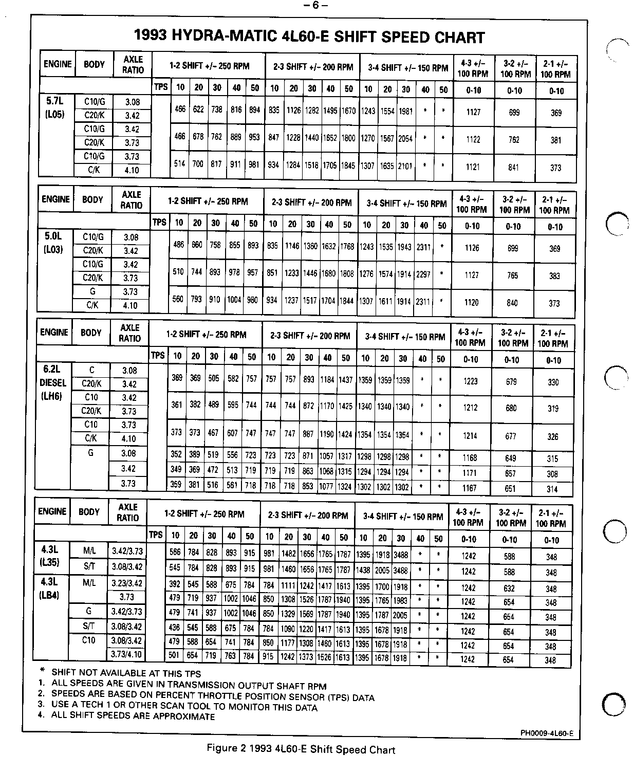
4. Clear codes, test drive car. Monitor powertrain with a TECH 1. For shift points refer to the shift speed chart, Figure 3. Remember when the gear selector is in D2 this will cause a 2nd gear start.
5. Recheck for stored codes. Correct all codes before continuing.
6. If transmission operates properly-stop.
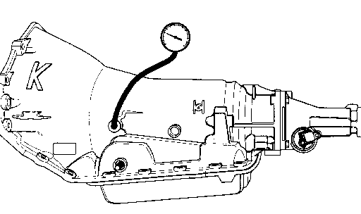
7. For a too harsh or too soft shift condition confirm correct cal prom, then perform transmission line pressure check procedure, Figure 4. If line pressure is too high or too low, replace the transmission with a SRTA unit.
8. For a poor performance condition verify engine performance, then refer to torque converter evaluation in Section 7A-14A of the 1993 Service Manual.
9. For a vibration or noise condition refer to torque converter vibration test procedure in Section 7A-14A
10. If all the steps check out okay and the transmission still does not function correctly, refer to Section 7A-l4A of the 1993 Service Manual for diagnosis information. If the diagnosis information determines that an internal component of the transmission needs to be serviced, then replace the transmission. Do not disassemble the transmission. See above list for replacement service part numbers.
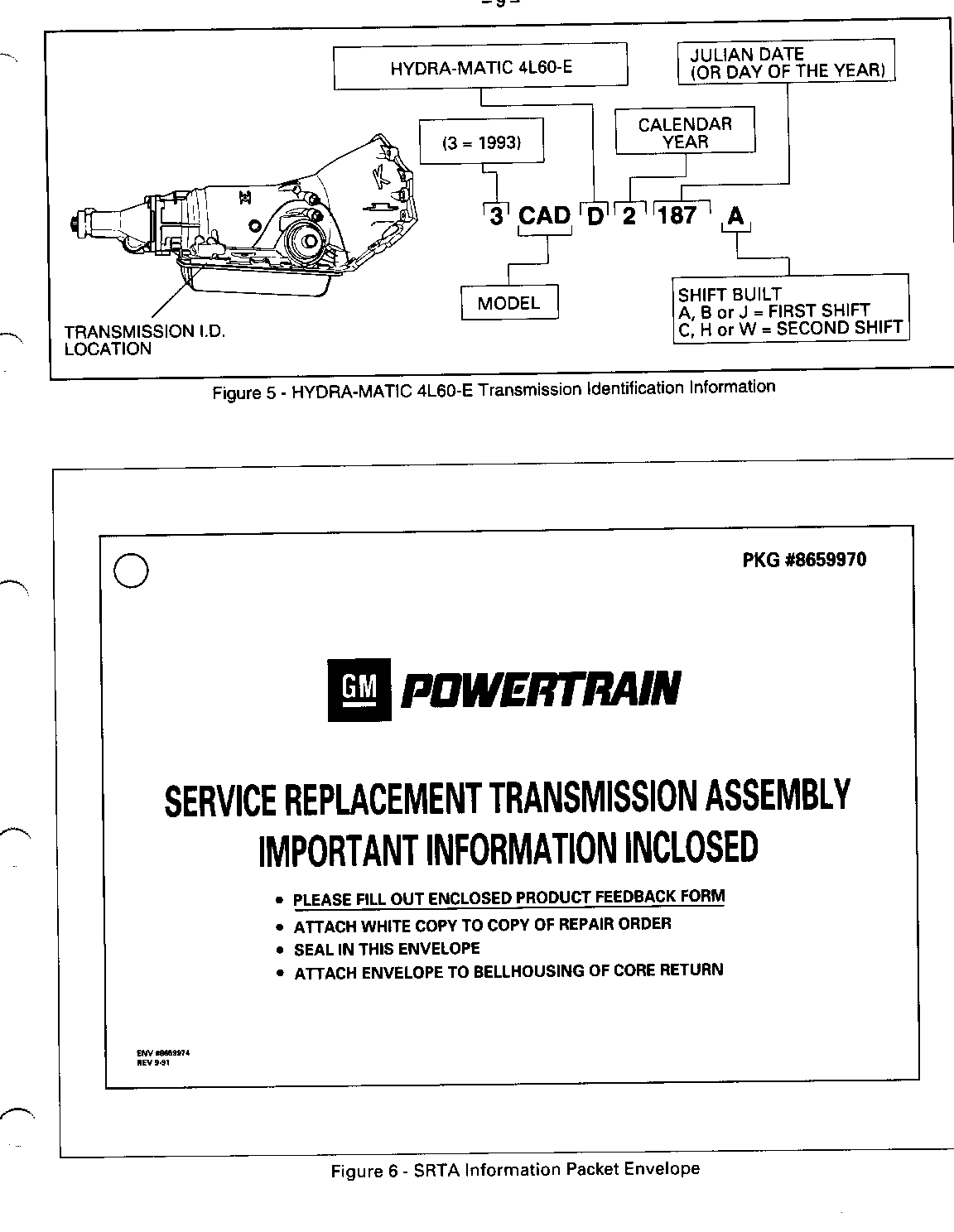
HYDRA-MATIC 4L60-E TRANSMISSION IDENTIFICATION INFORMATION
Transmission identification information and the SRTA model replacement chart will assist in selecting the correct SRTA unit to order from your local Parts Distribution Center.
SRTA PROCESSING PROCEDURE
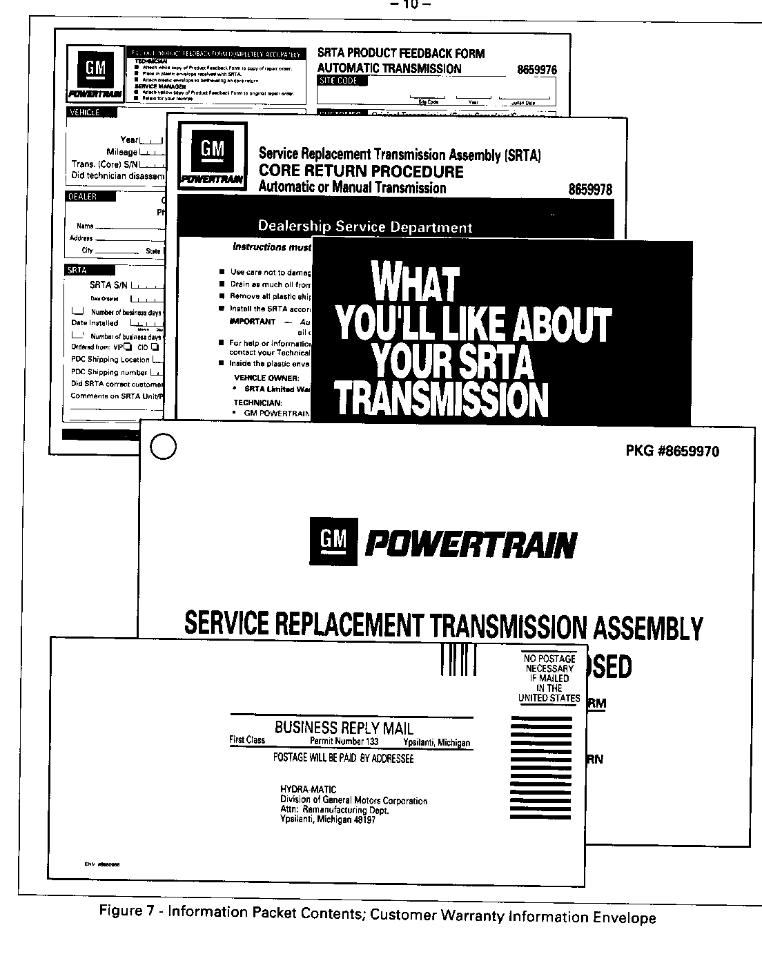
Each SRTA unit will be in a container which must be used for core return of the original HYDRA-MATIC 4L60-E assembly. A SRTA Information Packet is included with each SRTA unit. The contents of this envelope are to be removed and used as described with each illustration on the following pages.
SRTA PROCESSING PROCEDURES-INFORMATION PACKET
The contents of this envelope include Limited Warranty Information, Dealer Product Feedback Form, Core Exchange Return Procedure, and a pre-addressed return mailing envelope.
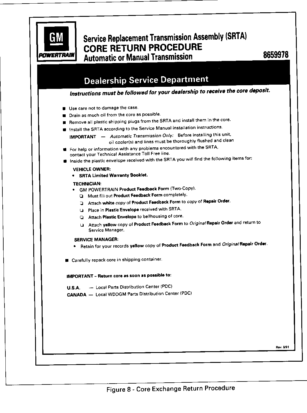
SRTA PROCESSING PROCEDURES-CORE EXCHANGE RETURN
The core return procedure provides detailed instructions for the GM dealer on handling the SRTA and original HYDRA-MATIC 4L60-E units. Refer to Chevrolet Policy and Procedures Manual, Article 1.7 for returning cores in a timely manner. Failure of the dealer to return a core will result in a charge of $700.00 to the dealer's open account.
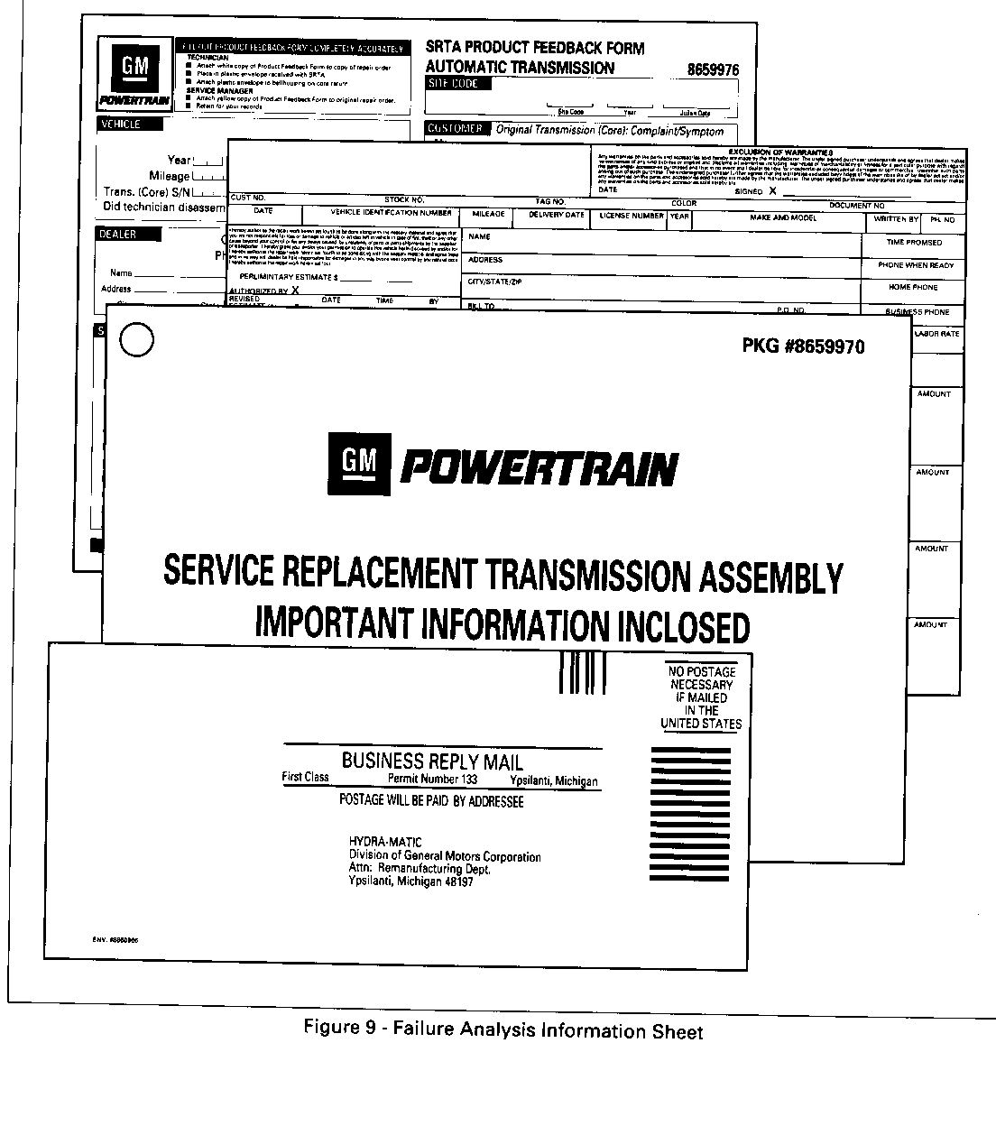
SRTA PROCESSING PROCEDURE-FAILURE ANALYSIS INFORMATION
This Product Feedback Form is to be completed by the service manager and/or technician. Fill out these forms as completely as possible to provide information which can be used for analysis. This valuable input can result in future product refinement through corrective action. Insert the white copy of the completed form and a copy of the repair order into the SRTA information Packet envelope, reseal the envelope and wire tag it to the bell housing of the unit being returned for core exchange. Return the yellow copy of the completed Product Feedback form, using the pre-addressed postage paid envelope, to Hydra-matic Division.
HYDRA-MATIC 4L60-E LINE PRESSURE CHECK PROCEDURE
Line pressures are calibrated for two sets of gear ranges - Drive-Park-Neutral and Reverse. This allows the transmission line pressure to be appropriate for different pressure needs in different gear ranges:
Gear Range Line Pressure Range ---------- ------------------- Drive, Park or Neutral 55 - 189 PSI Reverse 64 - 324 PSI
Before performing a line pressure check, verify that the pressure control solenoid is receiving the correct electrical signal from the PCM:
1. Install a scan tool.
2. Start the engine and set parking brake.
3. Check for a stored pressure control solenoid diagnostic trouble code, and other diagnostic trouble codes.
4. Repair vehicle if necessary.
Inspect
. Fluid level (see Section 7A)
. Manual linkage
Install or Connect
. TECH 1 Scan tool
. Oil pressure gage at line pressure tap
5. Put gear selector in Park and set the parking brake.
6. Start engine and allow it to warm up at idle.
7. Access the "PCS Control- test on the TECH 1 scan tool.
8. Increase DESIRED PCS in 0.1 Amp increments and read the corresponding line pressure on the pressure gage. (Allow pressure to stabilize for 5 seconds after each current change.)
9. Compare data to the Drive-Park-Neutral line pressure chart below.
*NOTICE Total test running time should not exceed 2 minutes, or transmission damage could occur.
CAUTION
Brakes must be applied at all times to prevent unexpected vehicle motion.
If pressure readings differ greatly from the line pressure chart, refer to the Diagnosis Charts contained in this section.
The TECH 1 scan tool is only able to control the pressure control solenoid in Park and Neutral with the vehicle stopped. This protects the clutches from extremely high or low pressures in Drive or Reverse ranges.
Pressure Control Solenoid Current (Amp) Line Pressure (PSI) --------------------------------------- ------------------- 0.02 170 - 190
0.10 165 - 185
0.20 160 - 180
0.30 155 - 175
0.40 148 - 168
0.50 140 - 160
0.60 130 - 145
0.70 110 - 130
0.80 90 - 115
0.90 65 - 90
0.98 55 - 65
Pressures at 1500 RPM and 66 degrees Celsius (150 degrees Fahrenheit) Line pressure drops as temperature increases.
The transmission electrical connector is a very important part of the HYDRA-MATIC 4L60-E operating system. Anything that interferes with the electrical connection can cause the transmission to set Diagnostic Trouble Codes and/or operate incorrectly.
The following items can affect the electrical connection:
- Bent pins in the connector from rough handling during connection and disconnection
- Wires backing away from the pins or coming uncrimped (in either the transmission or vehicle wiring harness)
- Dirt contamination entering the connector when it is unconnected
- Pins in the connector backing out of the connector or pushed out during connection
- Excessive transmission fluid leaking into the connector, wicking up into the vehicle wiring harness and degrading the wire insulation *
- Water/moisture intrusion in the connector
- Low pin retention from excessive connection and disconnection of the wiring harness
- Pin corrosion from contamination
*The presence of transmission fluid in the transmission connector is not harmful in itself. The fluid only affects the vehicle harness wiring insulation if the fluid wicks up that far.
Points to remember when working with the transmission electrical connector:
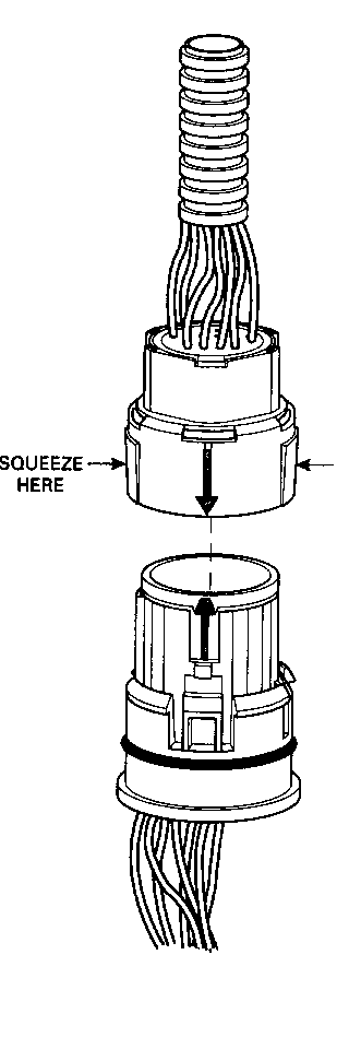
- To remove the connector, squeeze the two tabs towards each other and pull straight up (See illustration).
- Carefully limit twisting or wiggling the connector during removal. This can bend pins.
- DO NOT pry the connector off with a screwdriver or other tool.
- To install the connector, first orient the pins by lining up the arrows on each half of the connector. Push the connector straight down into the transmission without twisting or angling the mating parts.
- The connector should click into place with a positive feel and/or noise.
- Whenever the transmission pass-thru connector is disconnected from the vehicle harness and the engine is running, multiple Diagnostic Trouble Codes will set. Be sure to clear these codes after re-connecting the pass-thru connector.
DTC's 59, 67 and 82 will set with key on, engine off.
DTC's 59, 66, 67, 73 and 82 will set with key on, engine on.
General Motors bulletins are intended for use by professional technicians, not a "do-it-yourselfer". They are written to inform those technicians of conditions that may occur on some vehicles, or to provide information that could assist in the proper service of a vehicle. Properly trained technicians have the equipment, tools, safety instructions and know-how to do a job properly and safely. If a condition is described, do not assume that the bulletin applies to your vehicle, or that your vehicle will have that condition. See a General Motors dealer servicing your brand of General Motors vehicle for information on whether your vehicle may benefit from the information.
