Tools Required
| • | J 25025-5 Guide Pin |
| • | J 36850 Assembly Lubricant |
- Install the 8 control valve body ball check valves (54) into the case passages.
- Install the TCC solenoid valve screen assembly (75) into the case.
- Install the manual valve (319) into the control valve assembly.
- Install the J 25025-5 into the transmission case.
- Install the control valve body spacer plate gasket (48).
- Install the control valve assembly (44). Attach the manual valve (319) to the detent lever (711) while installing the control valve assembly (44).
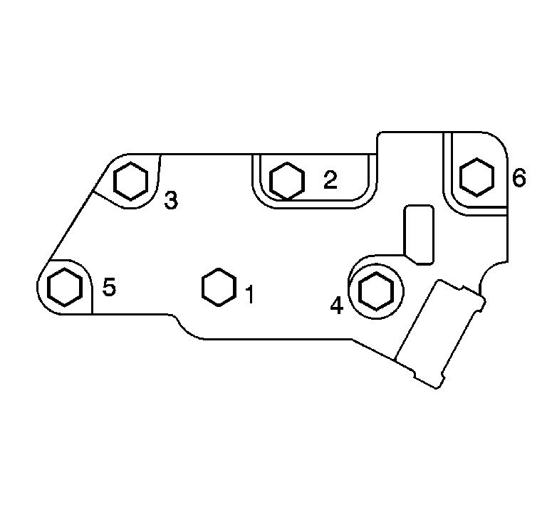
- Install the transmission fluid pressure manual valve position switch (40).
- Install the transmission fluid pressure manual valve position switch bolts (76) finger tight.
- Tighten the bolts in the order shown.
- Remove the J 25025-5 .
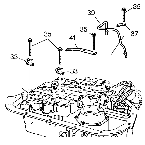
- Install the manual shift shaft detent spring assembly (41) and bolts (35).
- Install the 2 wiring harness clamps (33) and bolts (35).
- Install the lube oil pipe (39) with the short end into the control valve assembly.
- Install the lube oil pipe retainer (37) and the bolt (35).
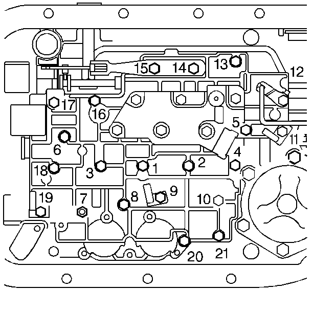
- Install the remaining control valve body assembly bolts (35).
- Tighten the control valve body assembly bolts in the order shown.

Notice: Use J 36850 or equivalent during assembly in order to retain checkballs or to lubricate components. Lubricants other than the recommended assembly lube changes the transmission fluid characteristics and causes undesirable shift conditions or filter clogging.
Use J 36850 or equivalent in order to hold the control valve body ball check valves in place.


Notice: Use the correct fastener in the correct location. Replacement fasteners must be the correct part number for that application. Fasteners requiring replacement or fasteners requiring the use of thread locking compound or sealant are identified in the service procedure. Do not use paints, lubricants, or corrosion inhibitors on fasteners or fastener joint surfaces unless specified. These coatings affect fastener torque and joint clamping force and may damage the fastener. Use the correct tightening sequence and specifications when installing fasteners in order to avoid damage to parts and systems.
Tighten
Tighten the bolts to 11 N·m (97 lb in).


Notice: Tighten the control valve assembly bolts in a spiral pattern starting from the center. If the bolts are tightened in a random pattern, the valve bores may become distorted, which can inhibit valve operation.
Tighten
Tighten the bolts to 11 N·m (97 lb in).
