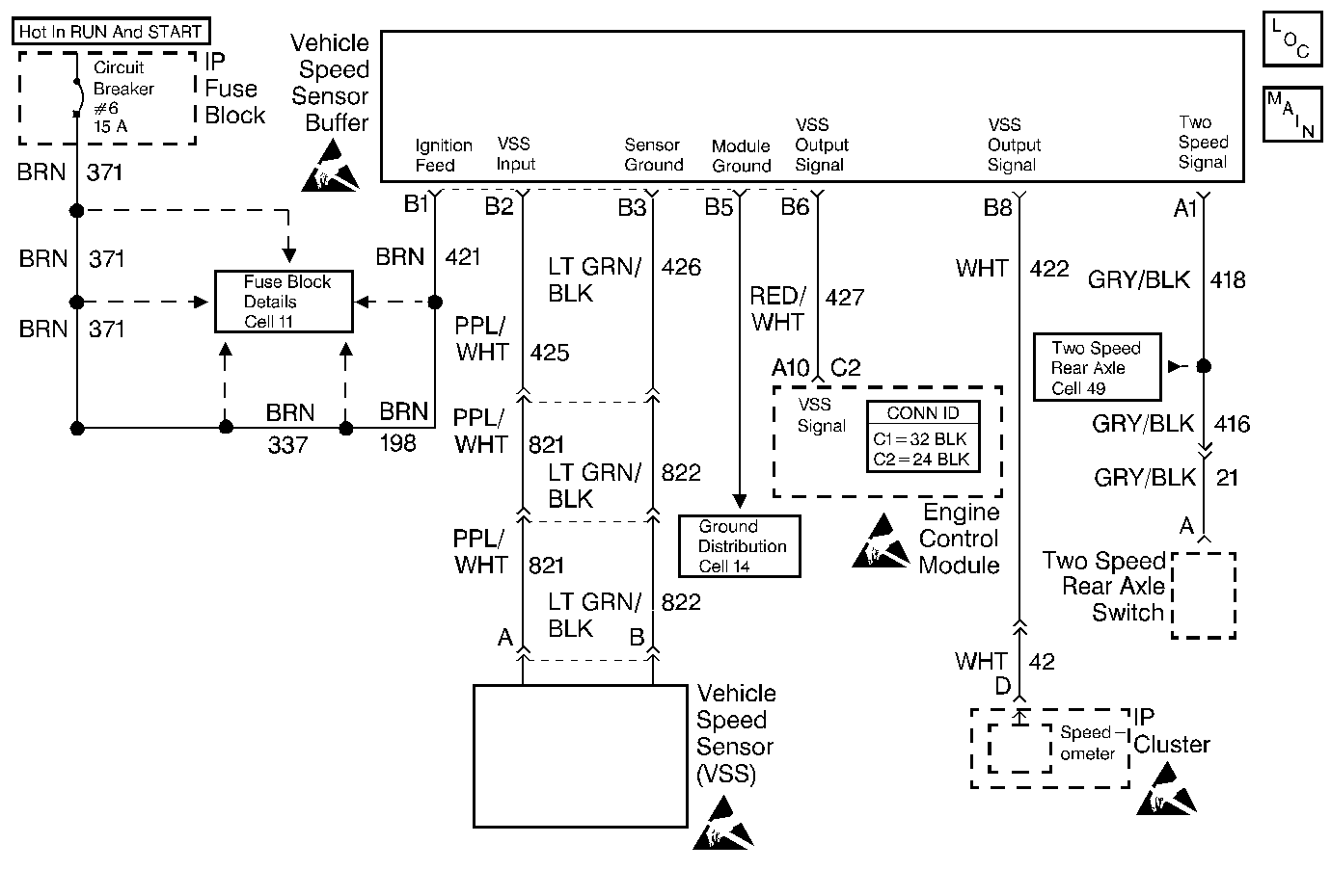
Circuit Description
The ECM applies and monitors 12 volts on the VSS signal circuit. The VSS signal circuit, connects to the VSS buffer module. The buffer module alternately grounds the VSS signal circuit, when receiving voltage pulses from the VSS sensor while the drive wheels are turning. This pulsing action takes place about 2,000 times per mile and the ECM will calculate the vehicle speed based on the time between pulses.
A scan tool reading should closely match the speedometer reading with drive wheels turning.
Conditions for Setting the DTC
| • | VSS signal circuit voltage constant |
| • | Engine speed more than 1,200 RPM |
| • | Vehicle speed signal indicates less than 2 mph (16 km/h) |
| • | All conditions must meet for 5 seconds |
| • | Vehicle in a road load deceleration |
Action Taken When the DTC Sets
The Malfunction Indicator Lamp (MIL) will illuminate.
Conditions for Clearing the MIL/DTC
The conditions for the fault are no longer present and 50 ignition cycles have passed with no further faults or the ignition switch is turned OFF and the battery feed voltage is removed for 10 seconds.
Diagnostic Aids
| • | Scan reading should closely match the speedometer reading, with drive wheels turning. |
| • | Check the neutral switch diagnosis table if the vehicle equipped with an automatic transmission. If the neutral switch is OK, refer to Intermittent Conditions . |
Test Description
The numbers below refer to the step numbers on the Diagnostic Table.
-
This test monitors the ECM voltage on the VSS signal circuit. With the wheels turning, the pulsing action will result in a varying voltage. The variation will be greater at low wheel speeds to an average of 4-6 volts at about 20 mph (32 km/h). A voltage of less than 1.0 volt at the ECM connector indicates that the VSS signal circuit is shorted to a ground. Disconnect the VSS signal circuit at the VSS buffer module. If voltage now reads above 10.0 volts, the VSS buffer module is faulty. If voltage remains less than 10.0 volts, then the VSS signal circuit wire is grounded. If the VSS signal circuit is not grounded, check for a faulty ECM connector or ECM. A steady 8-12 volts at the ECM connector indicates the VSS signal circuit is open or a faulty VSS buffer module.
-
This is normal voltage which indicates a possible intermittent condition.
Step | Action | Value(s) | Yes | No |
|---|---|---|---|---|
1 | Did you perform the On-Board Diagnostic (OBD) System Check? | -- | ||
2 |
Does the speedometer operate properly? | -- | Go to the Speedometer Diagnosis in Body and Accessories. | |
3 |
Does the scan tool indicate the vehicle speed above the specified value? | 0 km/h (0 mph) | Go to Diagnostic Aids | |
Is the voltage holding steady at the specified value? | 5.0-12.0 V | |||
Backprobe the VSS output circuit terminal at the VSS buffer module connector with a J 39200 DVM to ground with the wheels still turning. Does the voltage vary up to the specified value? | 10.0 V | |||
6 |
Did you find a problem? | -- | ||
7 |
Did you find a problem? | -- | ||
8 | Repair the open in the VSS output circuit. Is the action complete? | -- | -- | |
9 | Replace the VSS buffer module. Refer to Vehicle Speed Sensor Buffer Module Replacement . Is the action complete? | -- | -- | |
10 | Replace the ECM. Refer to Engine Control Module Replacement . Is the action complete? | -- | -- | |
11 |
Did the DTC reset? | -- | ||
12 | Are any DTCs stored which you have not diagnosed? | -- | Go to the Applicable DTC Table | System OK |
