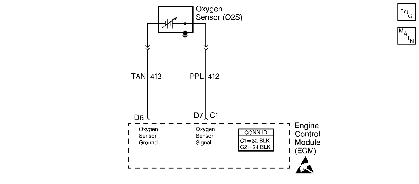
Circuit Description
The ECM supplies a voltage of about 0.45 volt between terminals D7 and D6. (If measured with J 39200 , this may read as low as 0.32 volt.). The oxygen sensor varies the voltage within a range of about 1.0 volt if the exhaust is rich to about 0.10 volt if exhaust is lean.
The sensor is like an open circuit and produces no voltage when it is below 315°C (600°F). An open sensor circuit or cold sensor causes an Open Loop operation.
Conditions for Setting the DTC
| • | Engine at normal operating temperature. |
| • | At least 2 minutes engine time after start. |
| • | Oxygen sensor signal voltage steady between 0.35 and 0.55 volt. |
| • | Throttle Position (TP) sensor signal above 4%. |
| • | All conditions must meet for about 60 seconds. |
Action Taken When the DTC Sets
The Malfunction Indicator Lamp (MIL) will illuminate. The system will go Open Loop.
Conditions for Clearing the MIL/DTC
The conditions for the fault are no longer present and 50 ignition cycles have passed with no further faults or the ignition switch is turned OFF and the battery feed voltage is removed for 10 seconds.
Diagnostic Aids
Normal scan voltage varies between 100 mV to 999 mV (0.1 and 1.0 volt) while in Closed Loop. DTC 13 sets in 1.0 minute if voltage remains between 0.35 and 0.55 volt, but the system will go to Open Loop in about 15 seconds. Refer to Intermittent Conditions .
Test Description
The numbers below refer to the step numbers on the Diagnostic Table.
-
If the conditions for a DTC 13 exist, the system will not go Closed Loop.
-
This step determines if the sensor is at fault or if the wiring or ECM is the cause of DTC 13.
-
In doing this test, use only a J 39200 . This test checks the continuity of the O2S signal circuit and the O2S ground circuit if the O2S ground circuit is open the ECM voltage on the O2S signal circuit will be over 0.6 volt (600 mV).
Step | Action | Value(s) | Yes | No |
|---|---|---|---|---|
1 | Did you perform the On-Board Diagnostic (OBD) System Check? | -- | ||
Does the scan tool indicate a Closed Loop? | 80°C (176°F) 1200 RPM | Go to Diagnostic Aids | ||
Does the scan tool indicate less than the specified voltage with the engine running? | 0.2 V | |||
Is the voltage less than the specified value? | 0.3 V | |||
5 |
Did you find a problem? | -- | ||
6 |
Did you find a problem? | -- | ||
7 |
Did you find a problem? | -- | ||
8 | Is the voltage greater than the specified value? | 0.6 V | ||
9 |
Did you find a problem? | -- | ||
10 |
Did you find a problem? | -- | ||
11 | Replace the Oxygen Sensor. Refer to Oxygen Sensor Replacement Is the action complete? | -- | -- | |
12 | Replace the ECM. Refer to Engine Control Module Replacement Is the action complete? | -- | -- | |
13 |
Did the DTC reset? | -- | ||
14 | Are any DTCs stored that have not been diagnosed? | -- | Go to the Applicable DTC Table | System OK |
