Product Safety - Inlet Elbow Fracture

| Subject: | 01019A -- Inlet Elbow Fracture |
| Models: | 2001 Chevrolet and GMC C-Series Medium Duty Vehicles |
| Equipped with an IMPCO Liquefied Petroleum Gas (LPG) Conversion Kit |
THIS BULLETIN CANCELS AND REPLACES BULLETIN 01019 ISSUED MAY, 2001. LABOR OPERATION V0738 IS BEING REVISED TO REFLECT A CORRECTION IN THE LABOR TIME. ALL COPIES OF BULLETIN 01019 SHOULD BE DESTROYED. | |
|---|---|
Condition
General Motors has decided that a defect which relates to motor vehicle safety exists in certain 2001 Chevrolet and GMC C-Series medium duty vehicles equipped with an IMPCO liquefied petroleum gas (LPG) conversion kit. Some of these vehicles have a condition in which the engine may backfire and fracture the plastic inlet elbow within the engine compartment. If this were to occur, and the hood of the vehicle were open, plastic fragments from the elbow could cause injury to people in the immediate area. In addition, the vehicle will stop running due to inadequate fuel supply.
Correction
Dealers are to install a temporary inlet elbow that is reinforced with a fiberglass wrap. The installation of this temporary elbow will eliminate the safety condition mentioned above. If an engine backfire should occur, the elbow could separate from its throttle body mounting, but would be retained. However, this would result in a disabled vehicle. GM is currently in the process of obtaining aluminum inlet elbows that will prevent the vehicle from becoming disabled due to the backfire condition. Customers will be notified when the aluminum inlet elbows are available, under a separate customer satisfaction campaign. In addition, GM has also redesigned the camshaft position sensor and the crankshaft position sensor to decrease the likelihood of backfire. These redesigned parts are currently available. Dealers are to inspect the camshaft and crankshaft position sensors to ensure the vehicle has the redesigned version.
Vehicles Involved
Involved are certain 2001 Chevrolet and GMC C-Series medium duty vehicles equipped with an IMPCO liquefied petroleum gas (LPG) conversion kit. Dealers should confirm vehicle eligibility through GMVIS (GM Vehicle Inquiry System) before beginning campaign repairs. [Not all vehicles within the above breakpoints may be involved.]
Involved vehicles have been identified by Vehicle Identification Number. Computer listings containing the complete Vehicle Identification Number, customer name and address data have been prepared, and are being furnished to involved dealers with the campaign bulletin. The customer name and address data furnished will enable dealers to follow-up with customers involved in this campaign. Any dealer not receiving a computer listing with the campaign bulletin has no involved vehicles currently assigned.
These dealer listings may contain customer names and addresses obtained from Motor Vehicle Registration Records. The use of such motor vehicle registration data for any other purpose is a violation of law in several states/provinces/countries. Accordingly, you are urged to limit the use of this listing to the follow-up necessary to complete this campaign.
Parts Information
Parts required to complete this campaign are to be obtained from two different sources. Please refer to your "involved vehicles listing" before ordering parts.
Important: Due to the uniqueness and small number of vehicles involved, and due to limited initial parts availability, dealers should not order campaign parts for use as shelf stock.
Parts required to install the camshaft and crankshaft position sensors are to be obtained from General Motors Service Parts Operations (GMSPO). Normal orders should be placed on a DRO = Daily Replenishment Order. In an emergency situation, parts should be ordered on a CSO = Customer Special Order.
Part Number | Description | Qty/ Vehicle |
|---|---|---|
12572656 | Sensor Asm, Cm/Sht Posn | 1 (If Req'd) |
12556427 | Sensor Asm, Cr/Sht Posn | 1 (If Req'd) |
Parts required to install the new inlet elbow, if necessary, are to be ordered directly from Quantum Technologies by calling 1-888-904-6726. DO NOT ORDER THIS PART FROM GMSPO.
Part Number | Description | Qty/ Vehicle |
|---|---|---|
103325 | Elbow Kit, Throttle Body Inlet (Temporary Elbow) | 1 |
Service Procedure
Camshaft Position Sensor Inspection
Inspect the camshaft position sensor for a part number and the presence of a blue paint stripe. The camshaft position sensor must be removed to inspect the part number on the mounting flange of the sensor and the presence of a blue paint stripe on the back of the sensor. Follow the removal procedure in the appropriate procedure found in SI2000. Follow the appropriate action listed in the table below.
Camshaft Sensor P/N | Action |
|---|---|
12565716 | Replace -- Install a new sensor following the replacement procedure in SI2000, then proceed to Crankshaft Position Sensor Inspection. |
12570674 with no paint stripe | Replace -- Install a new sensor following the replacement procedure in SI2000, then proceed to Crankshaft Position Sensor Inspection. |
12570674 with a blue paint stripe | OK -- No replacement necessary. Proceed to the Crankshaft Position Sensor Inspection. |
12572656 | OK -- No replacement necessary. Proceed to the Crankshaft Position Sensor Inspection. |
Crankshaft Position Sensor Inspection
Inspect the crankshaft position sensor for a part number and a date code. The crankshaft position sensor must be removed to inspect the date code located on the mounting flange of the sensor. Follow the crankshaft procedure removal procedure below to remove and inspect the sensor. Follow the appropriate action listed in the table below.
Crankshaft Sensor P/N | Action |
|---|---|
12556427, date code of 0285 or less | Replace -- Install a new sensor following the crankshaft position sensor replacement procedure below Then proceed to the Inlet Elbow Replacement procedure. |
12556427, date code of 0286 or greater | OK -- No replacement necessary. Proceed to the Inlet Elbow Replacement procedure. |
Crankshaft Position (CKP) Sensor Replacement
Important: Care must be taken when removing the CKP sensor. Use penetrating oil and allow to soak around the CKP sensor before removing the sensor. Twist the sensor to break the O-ring seals loose. When removing the sensor, pull the sensor straight out of the engine block at the same angle that the sensor was installed. Handle the CKP sensor carefully to prevent damage to the sensor.
Removal Procedure
- Disconnect the CKP sensor harness connector at the CKP sensor.
- Use penetrating oil and allow to soak around the CKP sensor before removing the sensor.
- Remove the CKP sensor retaining bolt.
- Prior to removal of the CKP sensor, rotate the sensor so that the mounting flange faces the opposite direction.
- Remove the CKP sensor at the same angle that the sensor was installed.
Installation Procedure
- Install the CKP sensor at the same angle as you removed it.
- Install the CKP sensor retaining bolt.
- Connect the CKP sensor harness connector.
- Perform the CKP System Variation Learn Procedure. Follow the procedure in SI2000.
- Proceed to the Inlet Elbow Removal Procedure.
Tighten
Tighten the bolt to 12 N·m (106 lb in).
Inlet Elbow Replacement
Removal Procedure
- Relieve the LPG fuel system pressure.
- Remove the fresh air duct.
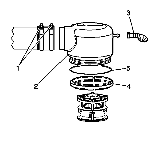
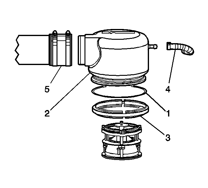
- Loosen the two air duct clamps (1) at the fuel mixer cover (2) and disconnect the duct from the cover.
- Disconnect the balance hose (3) from the fuel mixer cover.
- Loosen the fuel mixer cover clamp (4) and remove the clamp and gasket (5). Discard the gasket.
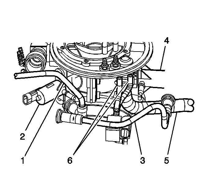
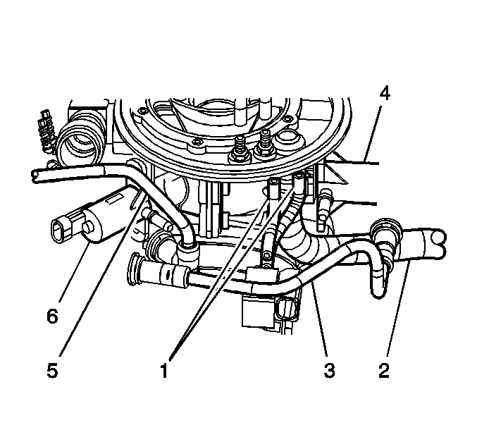
- Disconnect the electrical connector and the vacuum line (1) from the fuel control solenoid (FCS) (2).
- Disconnect the electrical connector and the fuel line (3) from the idle control solenoid (ICS) (4).
- Disconnect the oil breather hose (5) from the throttle body inlet elbow.
- Disconnect the two electronic throttle control (ETC) solenoid vacuum hoses (6) from the inlet elbow.
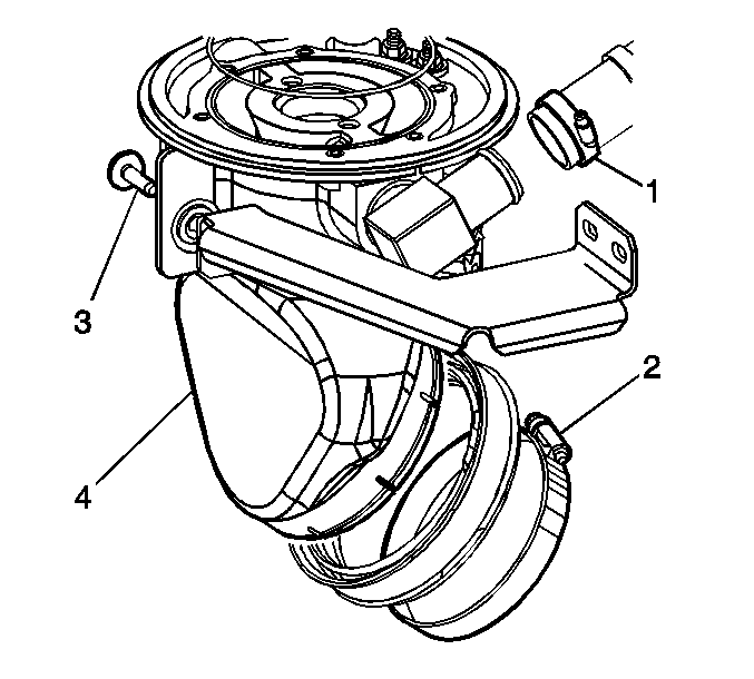
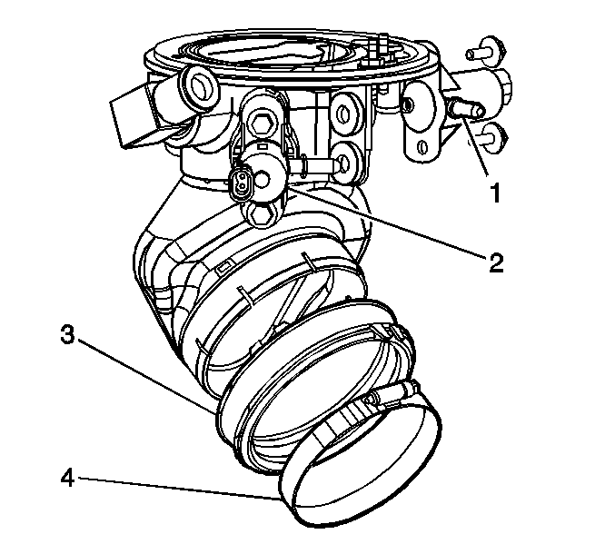
- Loosen the fuel vapor hose clamp (1) at the fuel inlet fitting.
- Loosen the hose clamp (2) at the throttle body.
- Remove the one front bracket to inlet elbow mounting bolt (3).
- Remove the two rear bracket to inlet elbow mounting bolts.
- Remove the fuel mixer and inlet elbow assembly (4) from the throttle body.
| 1.1. | Close the manual shut-off valve on the LPG fuel tank. |
| 1.2. | Start and operate the vehicle with the hood closed until the engine stalls. |
Disassembly Procedure
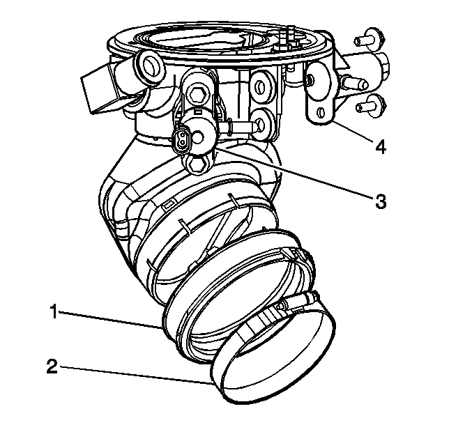
- Remove the rubber boot (1) and hose clamp (2) from the inlet elbow.
- Remove the two FCS mounting bolts and the FCS (3) from the inlet elbow.
- Remove the two ICS mounting bolts and the ICS (4) from the inlet elbow.
- Disconnect the two fuel mixer vacuum hoses (1) from the inlet elbow.
- Remove the six fuel mixer mounting bolts and the fuel mixer (2) from the inlet elbow.
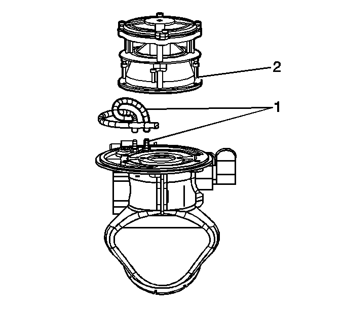
Assembly Procedure
- Verify that the new fuel mixer O-ring is installed in the groove (1) on the inlet elbow.
- Install the fuel mixer (2) and the six mounting screws to the inlet elbow.
- Connect the two fuel mixer vacuum hoses (3) to the inlet elbow.
- Install the ICS (1) and the two mounting bolts to the inlet elbow.
- Install the FCS (2) and the two mounting bolts to the inlet elbow.
- Install the rubber boot (3) and hose clamp (4) to the inlet elbow.
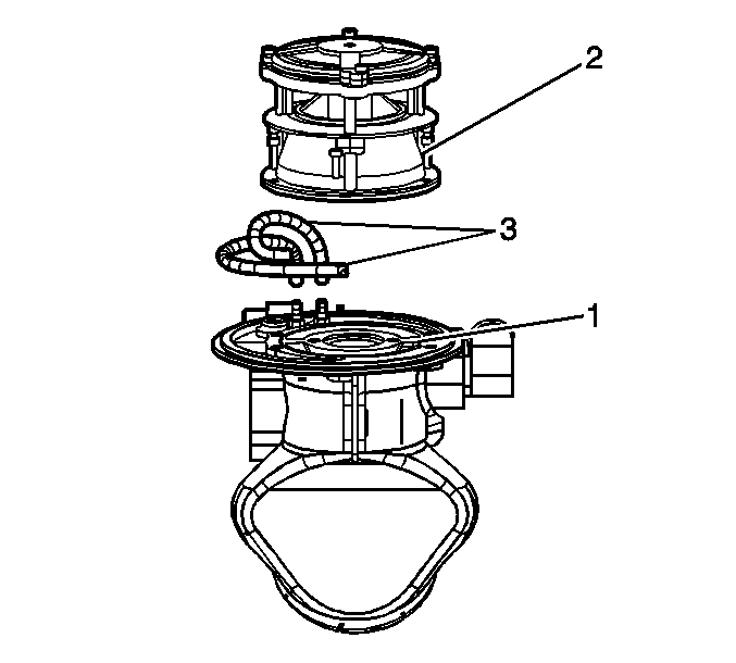
Tighten
Tighten the screws to 3.7 N·m (33 lb in).
Tighten
Tighten the bolts to 12 N·m (108 lb in).
Tighten
Tighten the bolts to 12 N·m (108 lb in).
Installation Procedure
- Install the fuel mixer and the inlet elbow assembly (1) to the throttle body.
- Install the one front bracket to inlet elbow mounting bolt (2).
- Install the two rear bracket to inlet elbow mounting bolts.
- Tighten the hose clamp (3) at the throttle body.
- Tighten the fuel vapor hose clamp (4) at the fuel inlet fitting.
- Connect the two electronic throttle control (ETC) solenoid vacuum hoses (1) to the inlet elbow.
- Connect the oil breather hose (2) to the inlet elbow.
- Connect the electrical connector and the fuel line (3) to the idle control solenoid (ICS) (4).
- Connect the electrical connector and the vacuum line (5) to the fuel control solenoid (FCS) (6).
- Verify that the fuel mixer cover gasket (1) is installed on the inlet elbow.
- Install the fuel mixer cover (2) and the clamp (3).
- Connect the balance hose (4) to the fuel mixer cover.
- Connect the air duct (5) to the fuel mixer cover.
- Install the fresh air duct.
- Open the manual shut-off valve on the LPG fuel tank.
- Start and road test the vehicle.
- Install the GM Campaign Identification Label.
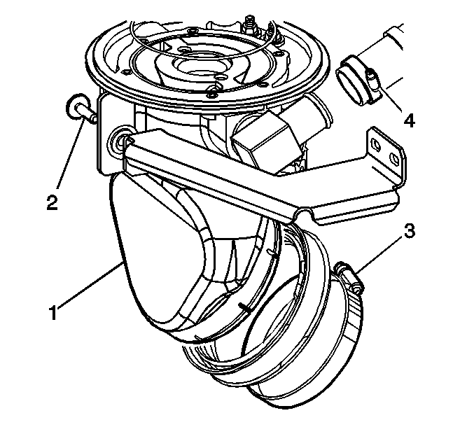
Tighten
Tighten the bolt to 12 N·m (108 lb in).
Tighten
Tighten the bolts to 12 N·m (108 lb in).
Tighten
Tighten the clamp to 5 N·m (45 lb in).
Tighten
Tighten the clamp to 2 N·m (18 lb in).
Tighten
Tighten the clamp to 5 N·m (45 lb in).
Tighten
Tighten the clamps to 5 N·m (45 lb in).
Campaign Identification Label
FOR US
Place a Campaign Identification Label on each vehicle corrected in accordance with the instructions outlined in this Product Campaign Bulletin. Each label provides a space to include the campaign number and the five (5) digit dealer code of the dealer performing the campaign service. This information may be inserted with a typewriter or a ball point pen.
Put the Campaign Identification Label on a clean and dry surface of the radiator core support in an area that will be visible to people servicing the vehicle. When installing the Campaign Identification Label, be sure to pull the tab to allow the adhesion of the clear protective covering. Additional Campaign Identification Labels for US dealers can be obtained from Dealer Support Material by calling 1-888-549-6152 (Monday-Friday, 8:00 am to 5:00 pm EST). Ask for Item Number S-1015 when ordering.
Claim Information
Submit a Product Campaign Claim with the information indicated below:
Repair Performed | Part Count | Part No. | Parts Allow | CC-FC | Labor Op | Labor Hours* | Net Item | ||||
|---|---|---|---|---|---|---|---|---|---|---|---|
Inspect & Replace, If Necessary, Camshaft and Crankshaft Position Sensors | 0-2 | -- | ** | MA-96 | V0737 | 1.3 | N/A | ||||
Install Temporary Inlet Elbow (Inc. Road Test) | 1 | N/A | N/A | MA-96 | V0738 | 1.1 | N/A | ||||
Floor Plan Reimbursement | 0 | N/A | N/A | MA-96 | V0739 | N/A | *** | ||||
* -- For Campaign Administrative Allowance, add 0.1 hours to the "Labor Hours". ** -- The "Parts Allowance" should be the sum total of the current GMSPO Dealer net price plus applicable Mark-Up for the sensor(s) needed to complete the repair. *** -- The amount identified in the "Net Item" column should represent the dollar amount shown below:
| |||||||||||
Refer to the General Motors WINS Claims Processing Manual for details on Product Campaign Claim Submission.
Floor Plan Reimbursement
Dealers in possession of vehicles included in the Stop Delivery are eligible for reimbursement of floor plan expense upon completion of this campaign. This reimbursement is limited to the number of days from the Stop Delivery message to receipt of the campaign parts and/or repair procedures. Floor plan reimbursement beyond these dates is not allowed. The amount of reimbursement should be charged as a net amount expense using the campaign labor operation provided.
Customer Notification
Customers will be notified of this campaign on their vehicles by General Motors (see copy of customer letter included with this bulletin).
Dealer Campaign Responsibility
The US National Traffic and Motor Vehicle Safety Act provides that each vehicle which is subject to a recall campaign of this type must be adequately repaired within a reasonable time after the customer has tendered it for repair. A failure to repair within sixty days after tender of a vehicle is prima facie evidence of failure to repair within a reasonable time. If the condition is not adequately repaired within a reasonable time, the customer may be entitled to an identical or reasonably equivalent vehicle at no charge or to a refund of the purchase price less a reasonable allowance for depreciation. To avoid having to provide these burdensome remedies, every effort must be made to promptly schedule an appointment with each customer and to repair their vehicle as soon as possible. In the recall campaign notification letters, customers are told how to contact the US National Highway Traffic Safety Administration if the campaign is not completed within a reasonable time.
All unsold new vehicles in dealers' possession and subject to this campaign MUST be held and inspected/repaired per the service procedure of this campaign bulletin BEFORE customers take possession of these vehicles.
Dealers are to service all vehicles subject to this campaign at no charge to customers, regardless of mileage, age of vehicle, or ownership, from this time forward.
Customers who have recently purchased vehicles sold from your vehicle inventory, and for which there is no customer information indicated on the dealer listing, are to be contacted by the dealer. Arrangements are to be made to make the required correction according to the instructions contained in this bulletin. This could be done by mailing to such customers a copy of the customer letter accompanying this bulletin. Campaign follow-up cards should not be used for this purpose, since the customer may not as yet have received the notification letter.
In summary, whenever a vehicle subject to this campaign enters your vehicle inventory, or is in your dealership for service in the future, please take the steps necessary to be sure the campaign correction has been made before selling or releasing the vehicle.
May, 2001Dear GM Customer:
Recently you were notified of a safety condition on your 2001 liquefied petroleum gas (LPG) fueled medium duty vehicle in which an engine backfire could fracture a plastic inlet elbow within the engine compartment. If this were to occur, and the hood of the vehicle were open, plastic fragments from the elbow could cause injury to people in the immediate area. In addition, the vehicle will stop running due to inadequate fuel supply. We also informed you of four precautions, listed below, that you could take to reduce any potential injury.
| • | Do not start or run the vehicle with the hood open. |
| • | All servicing of the vehicle that requires the hood to be open and the vehicle running should be suspended. |
| • | Do not operate the vehicle with the LPG fuel tank at less than 1/4 fuel capacity. |
| • | Do not operate the vehicle with a temporary LPG fuel vent. |
Your Chevrolet/GMC dealer will install a temporary inlet elbow that is reinforced with a fiberglass wrap. The installation of this temporary elbow will eliminate the safety condition mentioned above. If an engine backfire should occur, the elbow could separate from its throttle body mounting, but would be retained. However, this would result in a disabled vehicle. GM is currently in the process of obtaining aluminum inlet elbows that will prevent the vehicle from becoming disabled due to the backfire condition. You will be notified when the aluminum inlet elbows are available. In addition, GM has also redesigned the camshaft position sensor and the crankshaft position sensor to decrease the likelihood of backfire. These redesigned parts are currently available. Your Chevrolet/GMC dealer will inspect the camshaft and crankshaft position sensors on your vehicle to ensure that you have the redesigned version. All of this service will be performed for you at no charge .
Please contact your Chevrolet/GMC dealer to schedule an appointment that is convenient for you. If your vehicle was held at the dealership or upfitter because of the inlet elbow condition, you should call your dealer to make sure that the dealer has performed this campaign before your truck was delivered to you. Should your dealer be unable to schedule a service date within a reasonable time, you should contact GMICT Customer Assistance Center at 1-800-862-4389.
If, after contacting the GMICT Customer Assistance Center, you are still not satisfied that we have done our best to remedy this condition without charge and within a reasonable time, you may wish to write the Administrator, National Highway Traffic Safety Administration, 400 Seventh Street, SW, Washington, DC 20590 or call 1-800-327-4236.
The attached customer reply card identifies your vehicle. Presentation of this card to your dealer will assist in making the necessary correction in the shortest possible time. If you no longer own this vehicle, please let us know by completing the attached and mailing it in the postage paid envelope.
We are sorry to cause you this inconvenience; however, we have taken this action in the interest of your safety and continued satisfaction with our products.
Chevrolet/Pontiac-GMC Division
General Motors Corporation
Enclosure
