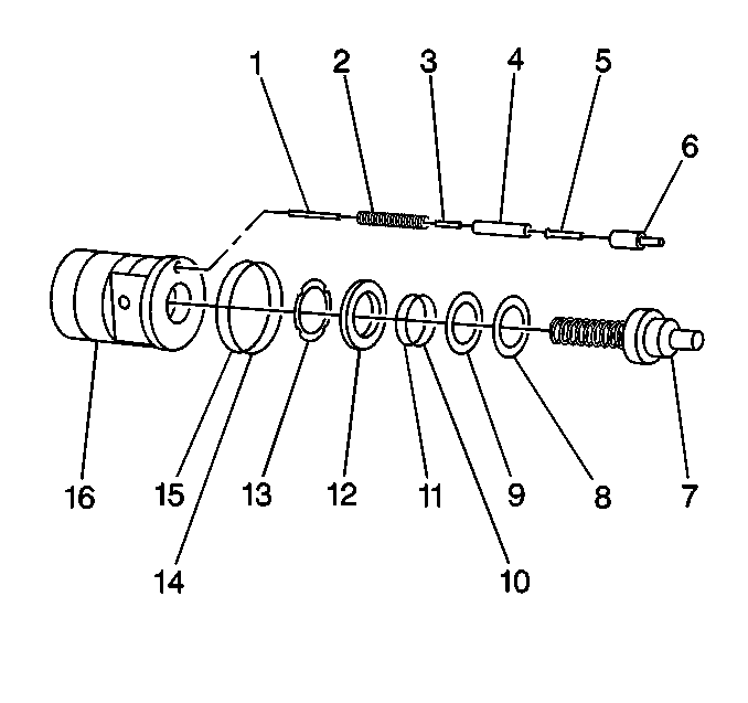
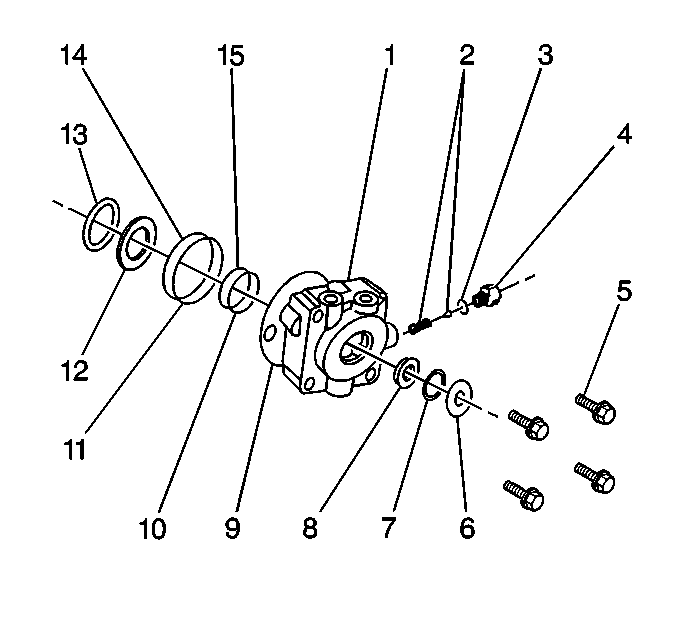
Valve Housing and Input Shaft Disassemble TRW Ross
Tools Required
J 37612-A TAS65
Complete Tool Kit
Disassemble the valve housing when the following conditions
exist:
| • | Maladjusted worm preload |

- Place the valve housing
and input shaft (7) assembly in a vise.
Ensure that the worm shaft is positioned vertically.
- Use a suitable punch in order to unstake the valve housing where
the valve housing was upset into the adjuster locknut slot.
- Unstake the adjuster nut from the adjuster.
- Use the J-37464 from the J 37612-A
in order to remove the bearing adjuster jam nut (13).
- Use the J-37070 from the J 37612-A
in order to remove the bearing adjuster (12).
- Remove the following components from the bearing adjuster:
- Remove the thin washer (9).
- Remove the thrust bearing (8).
- Remove the input shaft (7).
- Remove the valve.
- Remove the worm assembly.
- Remove the thrust bearing.

- Remove the thick thrust washer from the valve housing.
Important: Do not disassemble the input shaft and valve worm assembly further.
The components are a select fit at assembly and are available only as part
of this subassembly. If disassembled further, the subassembly must be
replaced.
- Remove the seals (15) and the O-ring (10) from the valve housing (1).
- Remove the retaining ring (7).
- Use a suitable socket against the exterior side of the seal in
order to remove the seal (14) from the valve housing.
Do not damage the valve housing bore.


