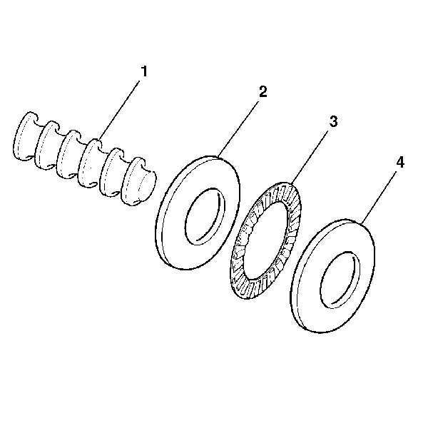
- Lubricate the following
items with power steering fluid:
| • | The roller thrust bearing (3) |
| • | The thrust bearing races (2) (4) |
- Install the following items over the end of the worm shaft (1)
Ensure that the angled surfaces on the thrust bearing races (2) (4)
are parallel to each other:
| • | The thrust bearing race (2) |
| • | The roller thrust bearing (3) |
| • | The thrust bearing race (4) |
- Lubricate the following items with power steering fluid:
| • | The valve body O-ring seals |
| • | The stub shaft O-ring seal |
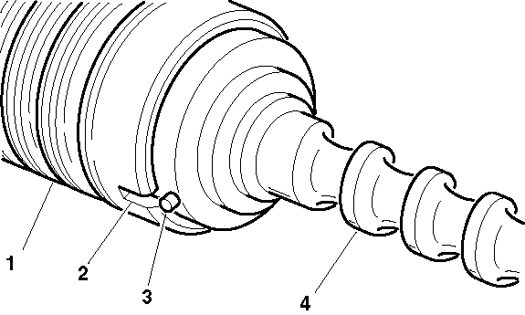
- Align the narrow notch (2)
in the valve body (1) with the pin (3) in the worm shaft cap.
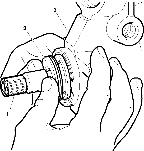
- Install the following
items into the steering gear housing (3) while applying pressure only
to the valve body (2):
| • | The worm shaft assembly |
- Ensure that the valve body (2) is properly seated when
the oil return hole in the steering gear housing is entirely uncovered.
- Apply oil to the O-ring seal.
- Install the O-ring seal onto the thrust support assembly.
- Place J 6222-A
over the end of the stub shaft (1).
- Push the thrust support assembly until the thrust support assembly
seats against the valve body.
Notice: Use the correct fastener in the correct location. Replacement fasteners
must be the correct part number for that application. Fasteners requiring
replacement or fasteners requiring the use of thread locking compound or sealant
are identified in the service procedure. Do not use paints, lubricants, or
corrosion inhibitors on fasteners or fastener joint surfaces unless specified.
These coatings affect fastener torque and joint clamping force and may damage
the fastener. Use the correct tightening sequence and specifications when
installing fasteners in order to avoid damage to parts and systems.
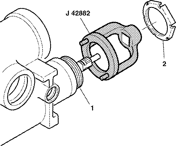
- Install the adjuster
nut assembly (1) into the steering gear housing until the adjuster
nut assembly (1) seats against the thrust support assembly.
Tighten
Tighten the adjuster nut assembly (1) to 28-31 N·m
(21-23 lb ft) using J 42882
.
- Install the coupling shield retainer and lock nut (2).
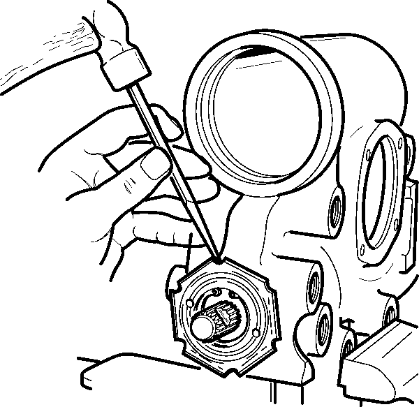
- Tighten the coupling shield
retainer (1) securely using a drift in a notch.
- Hold the adjuster nut assembly in order to maintain the alignment
of the marks while tightening the coupling shield retainer and lock nut (1).
Tighten
Tighten the coupling shield retainer and lock nut (1) to 108 N·m
(80 lb ft).
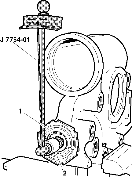
- Inspect the turning torque
using a ¾ inch 12-point socket (2) and J 7754-01
.
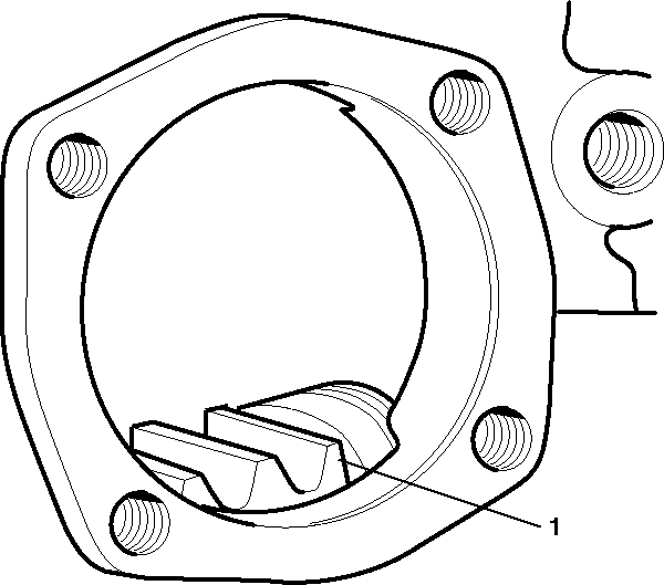
- Insert J 21552
into the bore of the primary rack piston (1).
- Push the primary rack piston (1) into the steering gear
housing with the teeth facing the pitman shaft opening until J 21552
contacts the center of the worm shaft.
- Turn the stub shaft clockwise to thread the primary rack piston
onto the worm shaft while holding J 21552
against the end of the worm.
- After threading the primary rack piston (1) completely
on the worm shaft, remove J 21552
from the primary rack piston (1).
- While looking through the side cover opening, center the primary
rack piston.
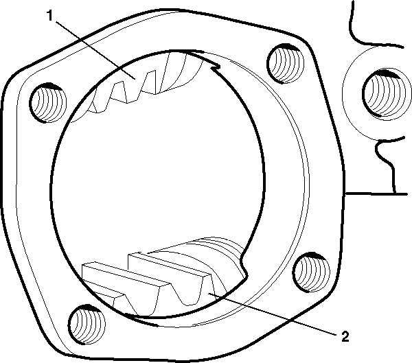
- Install the secondary
rack piston (2) into the steering gear housing with the teeth facing
the pitman shaft opening.
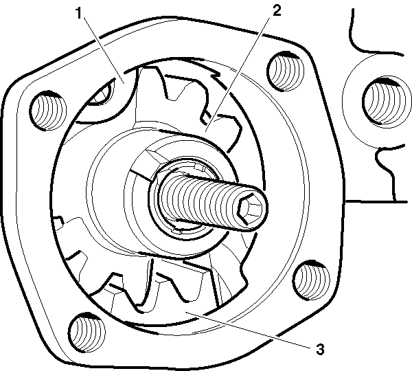
- Align the secondary rack piston teeth (2) with the primary
rack piston teeth (1).
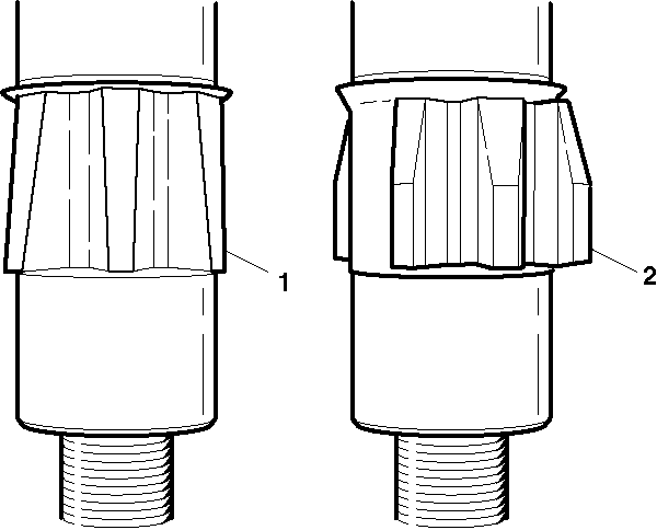
Important: The pitman shaft must be installed with the tapered teeth engaging the
primary rack piston. If this procedure is not followed, you will be impossible
to eliminate the lash between the primary gear teeth.
- Lubricate the area between the seal lips of the pitman shaft seal with
chassis lubricant or an all-purpose grease.
- Install pitman shaft (2)
into the steering gear housing.
- Install the side cover. Refer to
Steering Gear Pitman Shaft and Housing Cover Replacement - Off Vehicle
.
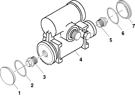
- Install the rack piston
plugs (3) (5) to both cylinders.
Tighten
If the rack piston plugs (3) (5) are aluminum, tighten
the rack piston plugs (3) (5) to 102 N·m (75 lb ft).
If the rack piston plugs (3) (5) are steel, tighten the rack
piston plugs (3) (5) to 115 N·m (85 lb ft).
- Install the housing end plug. Refer to
Steering Gear Housing Plug Replacement - Off Vehicle
.
Notice: Use the correct fastener in the correct location. Replacement fasteners
must be the correct part number for that application. Fasteners requiring
replacement or fasteners requiring the use of thread locking compound or sealant
are identified in the service procedure. Do not use paints, lubricants, or
corrosion inhibitors on fasteners or fastener joint surfaces unless specified.
These coatings affect fastener torque and joint clamping force and may damage
the fastener. Use the correct tightening sequence and specifications when
installing fasteners in order to avoid damage to parts and systems.
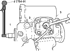
- In order to adjust
the pitman shaft preload, perform the following steps:
| 28.1. | Attach J 7754-01
and a 12-point socket (1) on the stub shaft splines. |
| 28.2. | Turn the stub shaft counterclockwise until bottomed. Count the
number of turns. |
| 28.3. | Turn the stub shaft back ½ the number of turns counted
above to centered position. |
| 28.4. | In order to check the combined ball and bearing preload, turn
the torque wrench (3) through the center of travel. Record the highest
reading. |
Tighten
| • | Tighten the adjuster screw on the pitman shaft until the torque
wrench reading is 0.7-1.1 N·m (6-19 lb in)
higher than the previous reading. The total reading should not exceed 2.25 N·m
(20 lb in) torque. |
| • | Tighten the preload adjuster nut (2) to 90 N·m
(66 lb ft). |
- Reinspect the preload after tightening the preload adjuster nut (2).


