Removal Procedure
- Remove the drum. Refer to Propeller Shaft Parking Brake Drum Replacement .
- Remove the companion flange retainer bolt.
- Remove the companion flange at the transmission mainshaft.
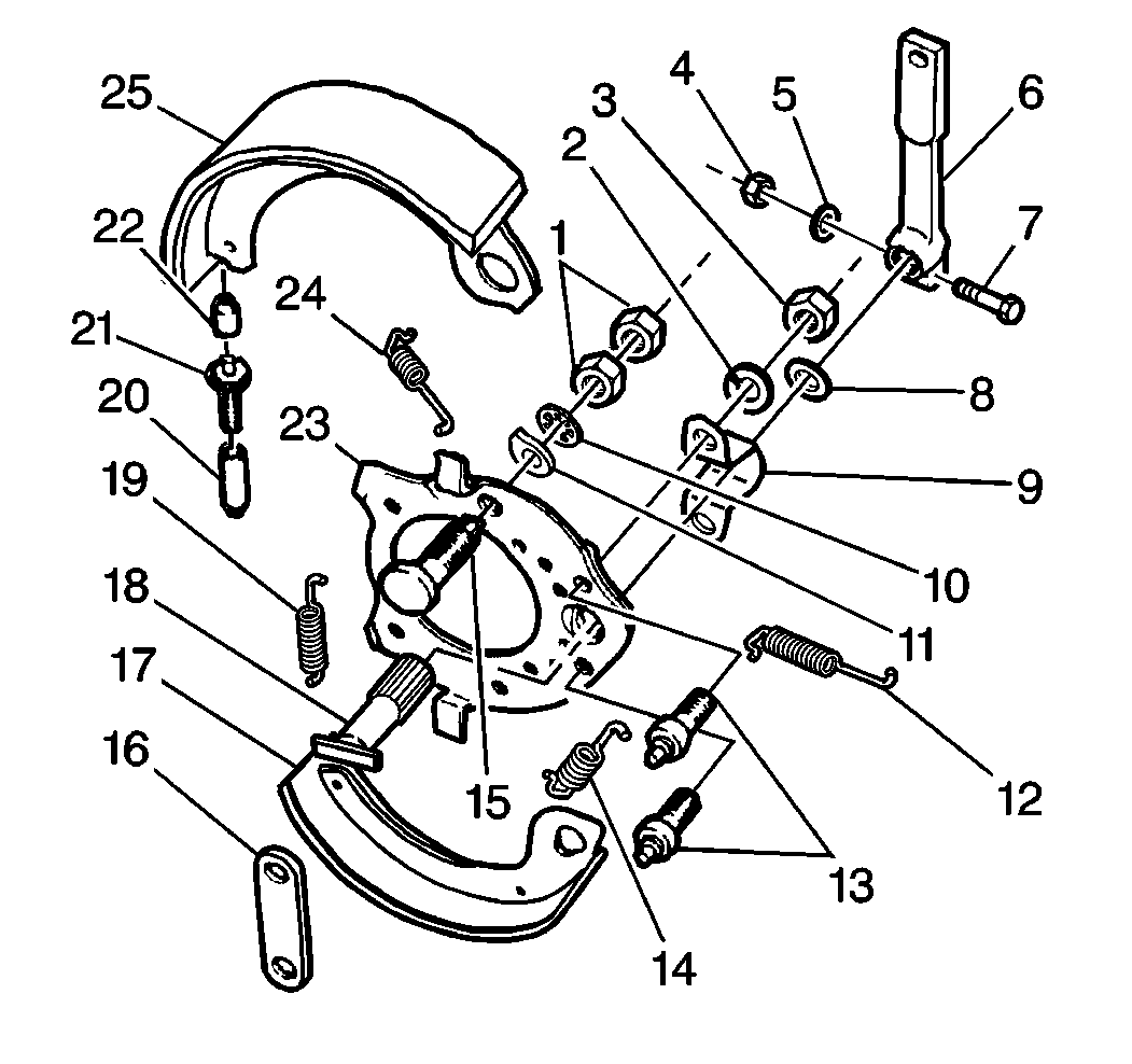
- Remove the cotter pin and the clevis pin that hold the clevis at the operating lever (6).
- Remove one return spring (12).
- Remove the link (16).
- Remove the second return spring (14).
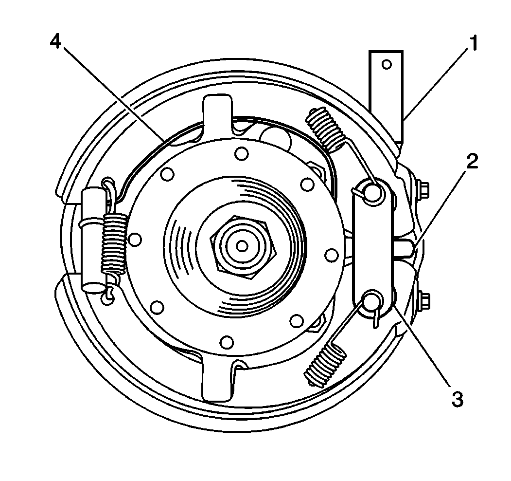
- Remove the operating lever (1).
- Mark the operating lever (1) and the camshaft (2) in order to ensure proper assembly.
- Loosen the clamping bolt and the nut.
- Use a brass or hardwood punch in order to free the camshaft (2) from the operating lever (1).
- Remove the washer (10).
- Remove the camshaft (18).
- Remove the anchor pin nuts (3) and the washers (3), if necessary.
- Remove the camshaft support bracket (9), if necessary.
- Remove the anchor pins (13), if necessary.
- Inspect the camshaft support bracket (9) and the anchor pins (13) for distortion.
- Replace the camshaft support bracket (9) and the anchor pins (13), if necessary.
- Inspect the surface of the camshaft (18) for excessive wear where there is contact with the shoe webs.
- Replace the camshaft (18) and shoe webs, if necessary.
- Inspect the anchor pins (13) and the nuts (3) for nicked or sheared threads.
- Replace the anchor pins (13) and the nuts (3), if necessary.
- Inspect the camshaft (2) and the operating lever (1) for worn or stripped splines.
- Replace the camshaft (2) and the operating lever (1), if necessary.


Installation Procedure
- Lubricate the threads of the anchor pins (13) with GM P/N 1051344 (Canadian P/N 993037) or equivalent.
- Install the anchor pins (13) if the anchor pins (13) were removed.
- Install the camshaft support bracket (9) if the camshaft support bracket (9) was removed.
- Install the spring washers (11) and the nuts (1).
- Coat the camshaft (18) with GM P/N 1051344 (Canadian P/N 993037) or equivalent.
- Spread the ends of the shoes apart.
- Center the camshaft (18) between the ends of the shoes.
- Install the camshaft (18) into the support plate (23) and the camshaft support bracket (9).
- Install the link (16).
- Install the return springs (14, 19).
- Coat the washer (2) with GM P/N 1051344 (Canadian P/N 993037) or equivalent.
- Install the washer (2).
- Line up the marks on the camshaft (2) and the operating lever (1).
- The operating lever (1) must be held against the washer with the camshaft (2) against the link (4).
- Install the operating lever (1).
- Wrap the return spring (24) around the camshaft support bracket (9) and attach the spring ends.
- Install the following items:
- Install the companion flange and the retainer bolt to the transmission mainshaft.
- Install the drum. Refer to Propeller Shaft Parking Brake Drum Replacement .
- Adjust the parking brake. Refer to Park Brake Adjustment .

Notice: Use the correct fastener in the correct location. Replacement fasteners must be the correct part number for that application. Fasteners requiring replacement or fasteners requiring the use of thread locking compound or sealant are identified in the service procedure. Do not use paints, lubricants, or corrosion inhibitors on fasteners or fastener joint surfaces unless specified. These coatings affect fastener torque and joint clamping force and may damage the fastener. Use the correct tightening sequence and specifications when installing fasteners in order to avoid damage to parts and systems.
Tighten
Tighten the nuts to 195 N·m (145 lb ft).

Tighten
Tighten the clamping bolt to 38 N·m (28 lb ft).

| • | The operating lever clevis |
| • | The clevis pin |
| • | The new cotter pin |
Tighten
Tighten the companion flange retainer bolt to 150 N·m (111 lb ft).
