Caution: Replace the steering gear mounting bolts, the washers and the nuts every
time you remove the steering gear from the vehicle. Failure to replace the
bolts, the washers and the nuts may cause the steering gear to separate from
the vehicle. This could cause a loss of steering control and personal
injury.
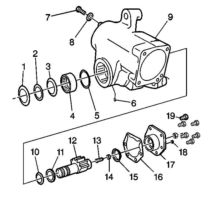
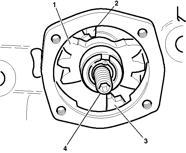
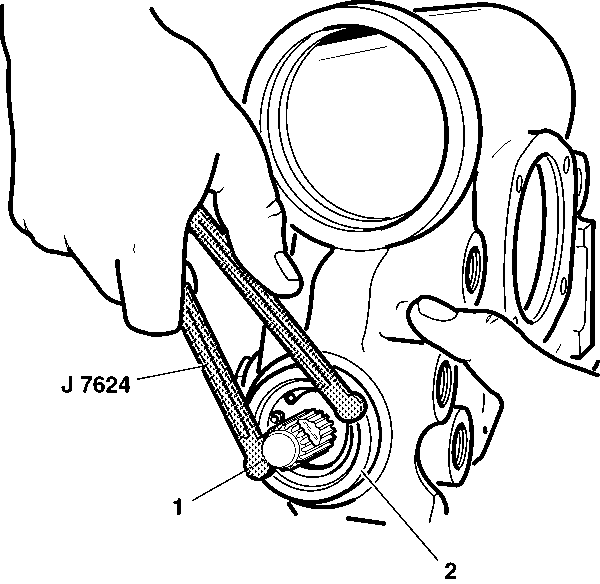
- Use a small screwdriver in order to remove
the dust seal (1).
- Remove the snap ring (2).
- Rotate the input shaft and valve worm assembly. Rotate the assembly
until the timing mark on the end of the sector shaft (12) is aligned with
the timing mark on the end of the housing trunnion.
- Use a fine grade emery cloth in order to remove any paint or corrosion
from the exposed area of the sector shaft (12).
- Remove the sector shaft adjusting screw jam nut.
- Use one layer of masking tape in order to tape the serrations
and the bolt groove on the sector shaft (12). Ensure that the tape
does not extend onto the sector shaft bearing diameter.
- Remove 6 bolts (19) from the side cover (17).
The bolts are equipped with a ring on the underside of the head. Replace
the bolts with the same type and length as necessary.
- Remove the side cover (17) and the sector shaft (12)
from the gear assembly (9) as a unit.
- Tap the end of the shaft lightly with a soft mallet. More fluid
will drain from the gear.
- Remove the gasket (16).
- Turn the sector shaft adjusting screw (13) clockwise.
- Remove the sector shaft (12) out of the side cover (17).
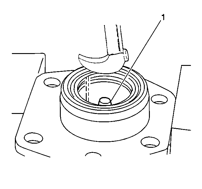
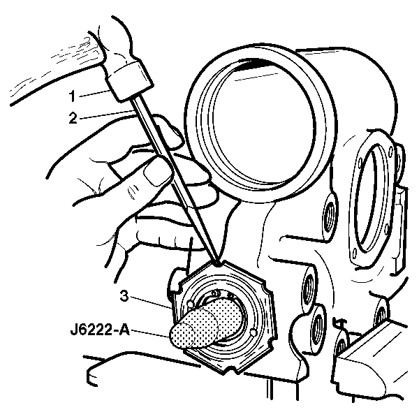
- Clamp the side cover in
a vise.
- Screw a ½-20 UNF 2Ax3 in bolt (1)
into the side cover adjusting screw hole. Ensure that the bolt end is positioned
in order to support a rolling head type pry bar.
- Support a pry bar in the bolt end of the seal.
Use
the pry bar in order to pry out the seal from the side cover.
Do not damage the seal bore or the bearing surface.
- Remove the bolt 1).
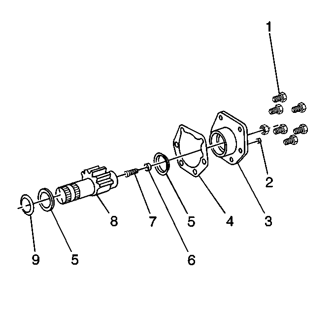
- Remove the vent plug (2).
- Inspect the adjusting screw (7) for damaged threads. The
screw must rotate by hand without perceptible end play.
- Inspect the retainer (6) . The retainer must be locked
in place without cracks.
- Place the sector shaft (8) firmly into a soft jawed vice.
Use a suitable chisel in order to unstake the retainer (6).
- Turn the retainer (6) out of the sector shaft pocket.
- Remove the adjusting screw (7).
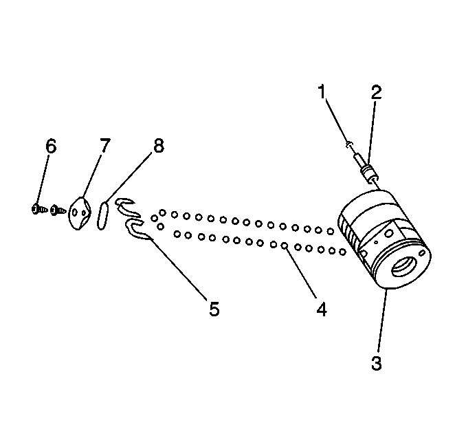
- Remove the relief valve cap (4), if equipped.
- Remove the O-ring (3), if equipped.
- Remove the two piece relief valve (2), if equipped.
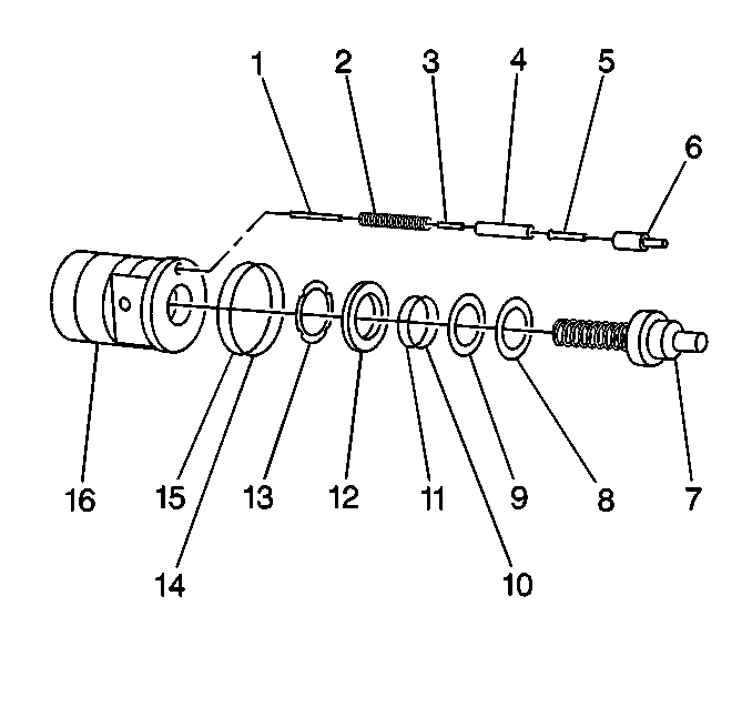
- Remove the seal (8).
- Use a fine grade emery cloth in order to clean any paint or corrosion
from the exposed area of the input shaft (7).
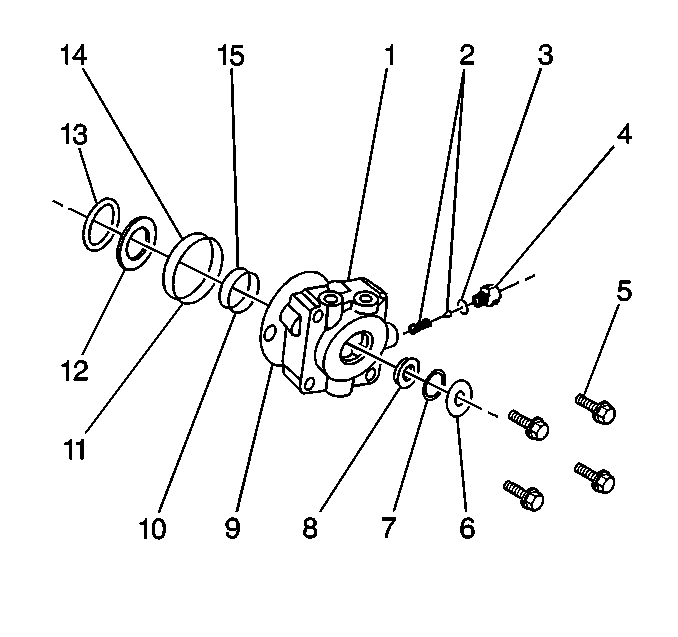
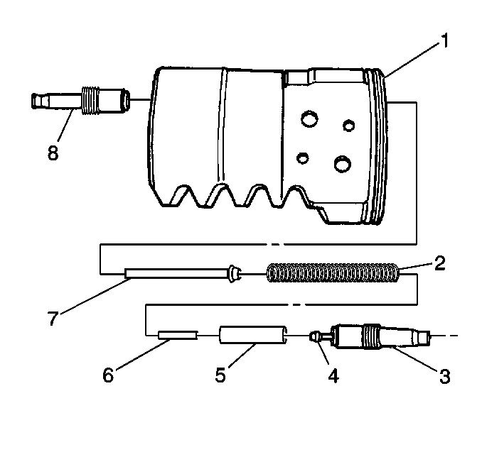
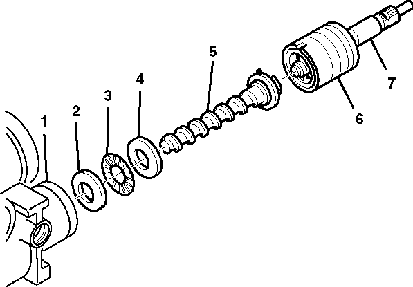
- Remove the bolts (5).
- Remove the following components as a unit from the housing:
- Place the assembly on
a clean cloth in order to catch the balls during the rack piston (3)
disassembly.
Do not remove the poppet adjuster seat and the
sleeve assemblies (2) unless the components will be replaced.
Do not disturb the position of the poppet adjuster seat unless the poppet
adjuster seat will be replaced.
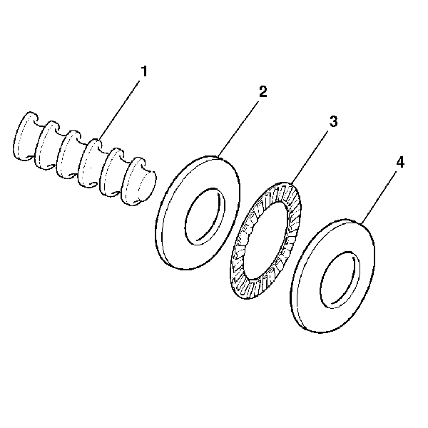
- Remove the seal rings.
- Remove the screws (6).
- Remove the cap (7).
- Remove the seal (8).
Important: Do not remove the input shaft, valve, worm assembly, or balls from the
rack piston until the ball return guides are removed or damage to the ball
guides will occur.
- Remove the ball return guide halves (5). Insert a small screwdriver
between the rack piston (3) and guides (5).
- Remove the 32 steel balls (4):
| 36.1. | Rotate the input shaft until all of the balls fall out. |
| 36.2. | The steel balls are a matched set. The set must be replaced if
any of the balls are lost. |
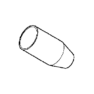
- Remove the rack piston (1)
from the input shaft.
- Remove the Teflon® seal ring and the O-ring.
- Remove the poppet assemblies, if necessary.
- Place the rack piston (1) in a soft-jawed vice.
- Use the J 36452-A in order to remove the larger diameter threaded
adjuster sleeve (3).
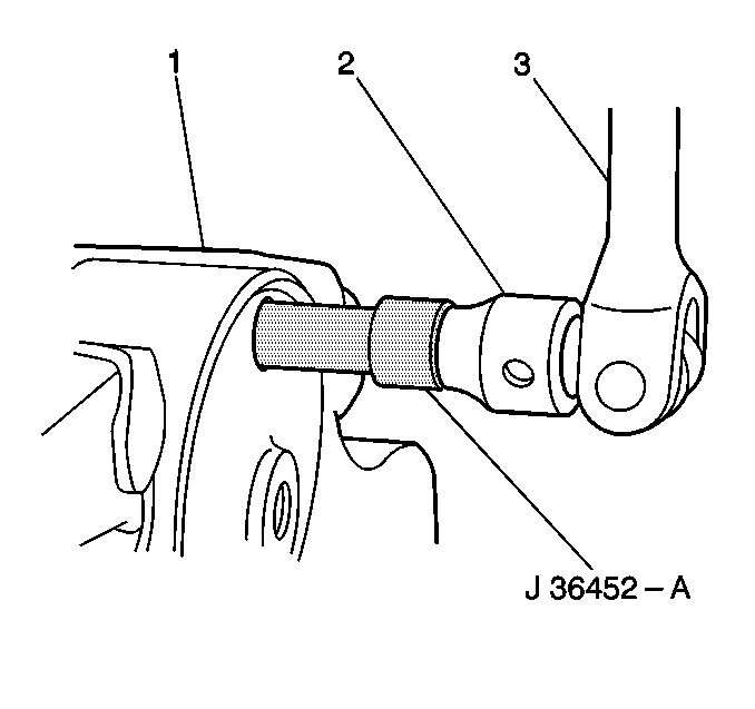
- Slide the J 36452-A over
the seat of the poppet adjuster seat and sleeve assemblies in the rack piston (1).
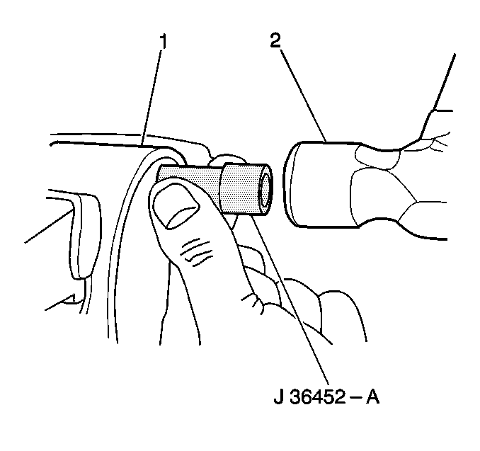
- Engage the tool in the
slots in the threaded sleeve.
- Hit the end of the tool firmly 3-4 times with a 0.45 kg
(16 oz) hammer (2) in order to loosen the Loctite that was
applied during assembly.
- Apply the breaker bar to the tool.
Use the tool in
order to turn the adjuster seat and the assemblies out of the rack piston (1).
Notice: The sleeve is retained with thread locking compound. A new rack piston
and poppet assembly will be required if they are damaged while removing the
sleeve.
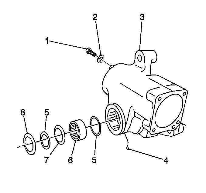
- Remove the poppet fixed
stop screw (1) and the washer (2), if necessary.
- Remove the grease fitting (4), if necessary.
- Remove the seal (7).
Use a small screwdriver
in order to remove the seal. Do not damage the sealing area of the bore.
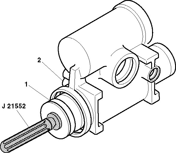
- Remove the bearing (6), if necessary.
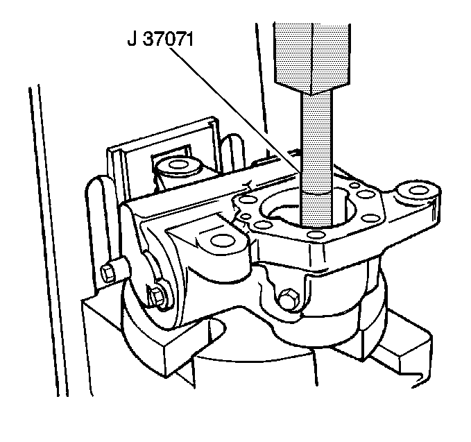
- Place the J 37071 against
the side cover end of the bearing.
Press the bearing out of the
trunnion end of the bearing bore.
- Ensure that the J 37071 clears the retaining ring.
- Remove the retaining ring, if necessary. Remove the retaining
ring through the trunnion end of the bearing bore in order to protect the
pressure seal bore area.

