Removal Procedure

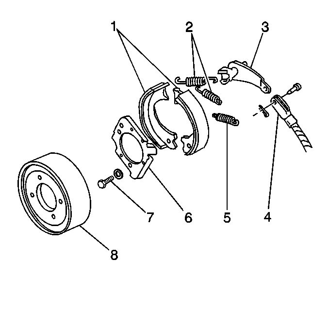
- Remove the drum (8). Refer
to
Brake Drum Replacement
.
- Remove the linings (1). Refer to
Parking Brake Shoe Replacement
.

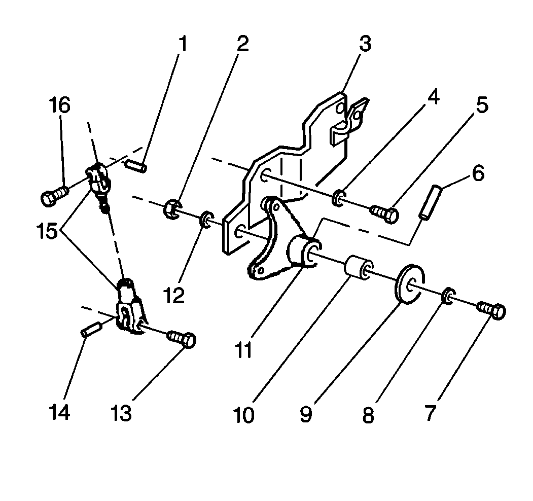
- Remove the 2 cotter
pins (1 and 14).
- Remove the 2 clevis pins (13 and 16).

- Remove the cam lever (3).
You may have to loosen the support plate (6) mounting bolts.

- Remove the cotter pin
(1) and the clevis pin (16) at the control cable arm of the bellcrank (11).
You may have to loosen the clevis jamb nut in order to relieve the binding
of the pin in the clevis.
- Remove the following items in order to remove the bellcrank bracket
(3) if the vehicle is equipped with a bellcrank bracket (3)
| • | The 2 bracket bolts (5 and 7) |
| • | The bellcrank (11) and bracket assembly |
- Remove the bellcrank pivot bolt nut (7) and the spring washer
(12), if equipped.
- Remove the bellcrank pivot bolt (7) and the two washers (8 and
9).
- Remove the bellcrank (11).
- Remove the bellcrank bushing (10).
- Inspect the bellcrank bushing (10) for wear.
Replace the bellcrank bushing (10) if necessary.
- Inspect the following items for wear, cracks and damage. Replace
these items if necessary.
- Inspect the bellcrank bracket (3) for damage, if equipped.
Replace the bellcrank bracket (3) if necessary.
Installation Procedure

- Install the bushing (10).
- Install the bellcrank (11) to the bracket (3), if equipped, or
directly to the transmission boss.
- Install the bellcrank pivot bolt (7) and the 2 washers
(8 and 9).
Notice: Use the correct fastener in the correct location. Replacement fasteners
must be the correct part number for that application. Fasteners requiring
replacement or fasteners requiring the use of thread locking compound or sealant
are identified in the service procedure. Do not use paints, lubricants, or
corrosion inhibitors on fasteners or fastener joint surfaces unless specified.
These coatings affect fastener torque and joint clamping force and may damage
the fastener. Use the correct tightening sequence and specifications when
installing fasteners in order to avoid damage to parts and systems.
- Install the bellcrank
pivot nut (2) and the spring washer (12), if equipped.
Tighten
| • | Tighten the nut on the assemblies with the bellcrank bracket to
38 N·m (28 lb ft). |
| • | Tighten the bolt on the assemblies mounted directly to the transmission
boss to 98 N·m (72 lb ft). |
- Install the bellcrank bracket (3), if equipped, with the assembled
bellcrank (11) to the transmission housing.
- Install the 2 bracket bolts (5 and 7) and the spring washers
(8 and 9), if equipped.
Tighten
Tighten the bolts to 30 N·m (22 lb ft).
- Install the control cable to the bellcrank (11):
| 7.1. | Insert the bellcrank arm into the slot in the control cable clevis. |
| 7.2. | Insert the clevis pin (16). |
| 7.3. | Install a new cotter pin (1). |
| 7.4. | Tighten the control cable clevis lock nut (2) if the nut is loosened. |
- Install the cam lever (3).

- Lubricate the socket in
the transmission case boss with GM P/N 1051344 or equivalent.

- Install the 2 clevis
pins (13 and 16).
- Install the 2 new cotter pins (1 and 14).
- Install the linings (1). Refer to
Parking Brake Shoe Replacement
.
- Install the drum (6). Refer to
Brake Drum Replacement
.


