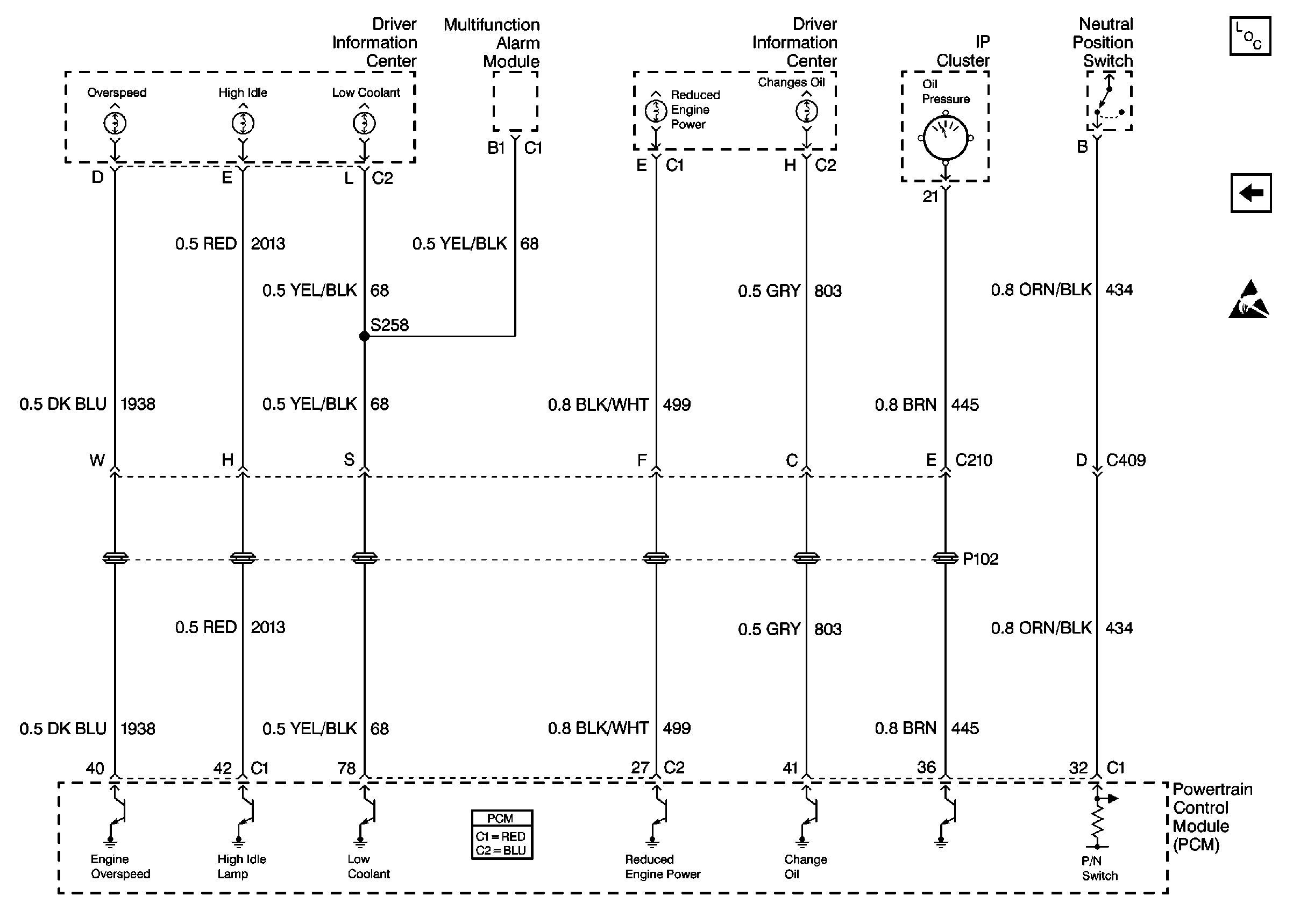
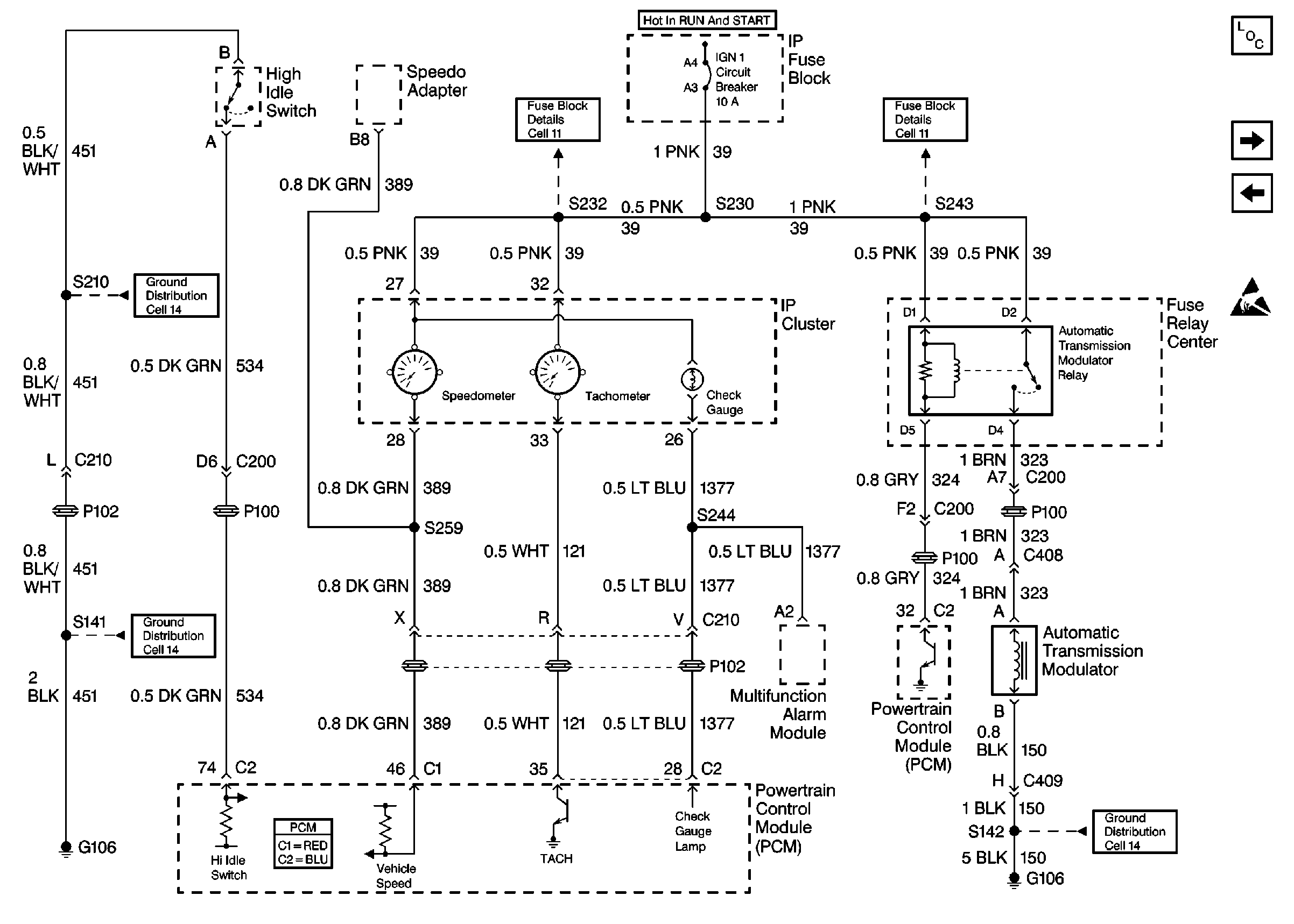
Refer to
Cell 20: Driver Information Center, Engine Controls

Cell 20: IP Cluster, Transmission Controls, Multifuction Alarm Module

Circuit Description
Ignition positive voltage is supplied to the FAST IDLE request circuit by the PCM. The PCM monitors the voltage at the FAST IDLE request circuit. When the FAST IDLE switch is depressed the FAST IDLE request circuit is connected to ground and the voltage on the circuit is pulled down to near 0 volts. The PCM will activate the FAST IDLE system if the following conditions exist:
| • | The PCM Fast Idle parameters are programmed into the PCM. Refer to Power Take-Off Fast Idle and Fast Idle System Programming . |
| • | The engine is running. |
| • | The vehicle speed is 0 km/h (0 mph). |
When the Fast Idle system is activated the following actions are taken:
- The engine speed is controlled by the Throttle Actuator Control (TAC) module. The engine speeds are determined by the PTO Options data list values that have been selected on the scan tool. Refer to . Power Take-Off Fast Idle and Fast Idle System Programming .
- The FAST IDLE lamp control circuit is grounded by the PCM and the lamp is turned ON.
The PCM will deactivate the FAST IDLE system and turn the FAST IDLE lamp OFF if any of the following exist:
- The engine is not running.
- The FAST IDLE switch is depressed and the voltage on the circuit is pulled down to near 0 volts.
- The vehicle speed is above 0 km/h (0 mph).
Test Description
The numbers below refer to the step numbers on the diagnostic table.
-
The specific Fast Idle engine speed options can be displayed and modified on the scan tool and are to be used as a guide to determine if the Fast Idle system is functioning properly. Refer to Power Take-Off Fast Idle and Fast Idle System Programming .
Step | Action | Value(s) | Yes | No | ||||||
|---|---|---|---|---|---|---|---|---|---|---|
1 | Did you perform the Powertrain On-Board Diagnostic (OBD) System Check? | -- | ||||||||
2 | Turn ON the ignition, with the engine OFF. Is the FAST IDLE lamp ON? | -- | ||||||||
Use the scan tool in order to view and record the selected PTO options and the selected Fast Idle engine speed values. Refer to Power Take-Off Fast Idle and Fast Idle System Programming . Is the action complete? | -- | -- | ||||||||
4 |
Did the engine speed correspond with the engine fast idle speed value selected on the scan tool? | -- | ||||||||
5 | Did the FAST IDLE lamp illuminate? | -- | System OK | |||||||
6 |
Did you find and repair a problem? | -- | ||||||||
7 |
Did the FAST IDLE lamp illuminate? | -- | ||||||||
8 | Check for the following conditions and repair as necessary:
Refer to Wiring Repairs in Wiring Systems. Is the action complete? | -- | Go to Step 2 | -- | ||||||
9 |
Did you find and repair a problem? | -- | ||||||||
10 |
Did you find and repair a problem? | -- | ||||||||
11 | Inspect the PCM connector for the following conditions and
Did you find and repair a problem? | -- | ||||||||
12 |
Important:: Program the replacement PCM. Refer to Powertrain Control Module Replacement . Replace the PCM. Is the action complete? | -- | -- |
