SERVICE MANUAL UPDATE SEC. 6A OIL PUMP COVER REPLACEMENT

Subject: OIL PUMP COVER REPLACEMENT
Model and Year: 1989-90 CELEBRITY WITH 2.5L ENGINE
The following Oil Pump Cover Replacement procedure updates and replaces the current procedure found in the 1989-90 A-Car Service Manuals.
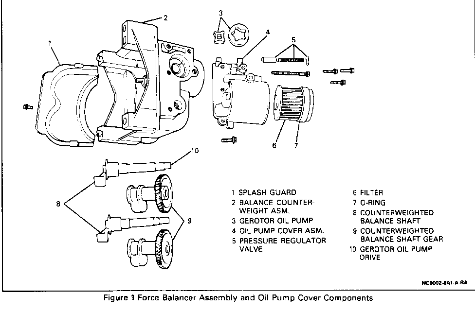
Oil Pump Cover
Figure 1
Tool Required: J 28467-A Engine Support Fixture
Remove or Disconnect
1. Negative battery cable. 2. Air cleaner and duct assembly. 3. Serpentine belt. 4. Engine torque strut from engine bracket. 5. Two upper front A/C compressor bolts to upper mounting bracket. 6. Install J 28467-A 7. Raise vehicle and suitably support. Refer to General Information (Section OA). 8. Right front tire and wheel assembly. Refer to Tires and Wheels (Section 3E). 9. Right side engine splash shield. 10. Exhaust pipe and converter. 11. Lower front A/C compressor mounting bolt and support bracket. 12. Rear A/C compressor mounting bracket bolts. 13. Wire harness from bell housing bracket. 14. Flywheel cover retaining bolts. 15. Starter and support bracket, set aside, Refer to Cranking System (Section 6D2). 16. Flywheel cover. 17. Engine support bracket bolts from engine. 18. Loosen transaxle mounting nuts. 19. Lower vehicle. 20. Raise front of engine about 3 inches, using J 28467-A. 21. Engine support bracket nuts from engine mount and frame assembly. Remove support bracket and mount. Refer to Frame and Underbody (Section 10-3). 22. Raise vehicle and suitably support. Refer to General information (Section OA). 23. Drain engine oil. 24. Using a jack stand, place a wood support along transaxle oil pan inside edge, raise transaxle and engine assembly to normal sitting position with J 28467-A in position. 25. Oil Pan retaining bolts. 26. Oil pan from engine block.
Clean
Engine block and oil pan surface. 27. Oil filter 28. Oil pump cover assembly. 29. Oil pump gears.
CAUTION:
THE PRESSURE REGULATOR VALVE SPRING IS UNDER PRESSURE. EXERCISE CAUTION WHEN REMOVING THE PIN, AS BODILY INJURY MAY RESULT.
30. Pressure regulator valve
Plug or pin Spring Valve If valve is stuck, clean the valve and pump housing with carburetor cleaning solvent.
CAUTION:
AVOID BREATHING THE FUMES, OR EXPOSURE OF THE SKIN TO THE CLEANING SOLVENT, AS BODILY INJURY MAY RESULT. WHEN WORKING OVERHEAD, WEAR EYE PROTECTION.
Clean
All parts of sludge, oil and varnish. Varnish on parts may be removed by soaking in carburetor or cleaning solvent.
Inspect
For foreign material and determine source. Pump housing and oil pump cover assembly for:
Cracks Scoring Casting imperfections
Pressure regulator valve for: Scoring Sticking. Burrs may be removed with a fine oil stone.
Pressure regulator valve spring for: Loss of tension Bending If in doubt, replace the spring
Screen assembly for: Looseness Broken wire mesh or screen
Gerotor oil pump for: Chipping Galling Wear
Measure Gerotor housing pocket depth Gerotor thickness
Important: When deciding pump serviceability based on pocket depth, consider depth of wear pattern in gear pocket and face oil pump cover assembly.
Install or Connect
1. Pack pump with petroleum jelly. Lubricate all internal parts with clean engine oil.
NOTICE: TO AVOID ENGINE DAMAGE, ALL PUMP CAVITIES MUST BE PACKED WITH PETROLEUM JELLY BEFORE INSTALLING THE GEARS TO ASSURE PRIMING.
2. Pressure regulator valve and spring. 3. Plug or pin Make sure pin is properly secured. 4. Oil pump gears. 5. Oil pump cover assembly. Tighten Bolts to 10 N.m (89 lbs. in.). 6. Oil filter. 7. Apply RTV sealer GM P/N 12345739 or equivalent. 8. Oil pan to engine block. 9. Oil pan retaining bolts. Tighten Bolts to 1 0 N.m (89 lbs. in.). 10. Remove jack stand and wood support. 11. Lower vehicle. 12. Fill engine oil. Refer to Maintenance and Lubrication (Section 0B).
NOTICE: IF THE OIL PRESSURE DOES NOT BUILD UP ALMOST IMMEDIATELY, REMOVE THE OIL PAN AND EXAMINE PUMP. IF NECESSARY, DISASSEMBLE THE OIL PUMP AND REPACK ALL CAVITIES WITH PETROLEUM JELLY. RUNNING THE ENGINE WITHOUT MEASURABLE OIL PRESSURE WILL CAUSE EXTENSIVE DAMAGE.
Inspect
Remove the oil pressure sending unit and install an oil pressure gage. Start engine and observe oil pressure. Check for bearing knock. If necessary, disassemble and check for adequate oil supply and proper clearance.
13. Engine support bracket and nuts to engine mount. Tighten Nuts to 47 N.m (35 lbs. ft.). 14. Engine mount and nuts to frame assembly. Tighten Nuts to 47 N.m (35 lbs. ft.). 15. Lower front of engine. 16. Raise vehicle. 17. Transaxle mounting nuts. Tighten Nuts to 50 N.m (37 lbs. ft.). 18. Engine support bracket bolts to engine. Tighten Bolts to 50 N.m (37 lbs. ft.). 19. Flywheel cover. 20. Starter assembly and support bracket. Refer to Cranking System (Section 6D2). 21. Flywheel cover attaching bolts. Tighten Bolts to 10 N.m (89 lbs. in.). 22. Wire harness at bell housing bracket. 23. Rear A/C compressor mounting bracket bolts. Tighten Bolts to 25 N.m (1 8 lbs. ft.). 24. Lower front A/C compressor mounting bolts and support brace. 25. Exhaust pipe and converter. 26. Right side engine splash shield. 27. Right front tire and wheel assembly. Refer to Tires and Wheels (Section 3E). 28. Lower vehicle. 29. Remove J 28467-A. 30. Upper front A/C compressor to mounting bracket bolts. Tighten Bolts to 25 N.m (1 8 lbs. ft.). 31. Engine torque strut to engine bracket. 32. Serpentine belt. 33. Air cleaner and duct assembly. 34. Negative battery cable.
Inspect Oil level

General Motors bulletins are intended for use by professional technicians, not a "do-it-yourselfer". They are written to inform those technicians of conditions that may occur on some vehicles, or to provide information that could assist in the proper service of a vehicle. Properly trained technicians have the equipment, tools, safety instructions and know-how to do a job properly and safely. If a condition is described, do not assume that the bulletin applies to your vehicle, or that your vehicle will have that condition. See a General Motors dealer servicing your brand of General Motors vehicle for information on whether your vehicle may benefit from the information.
