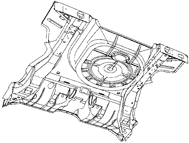
Rear Floor Assembly Sectioning Procedure
Use the sectioning procedures in order to repair the rear floor. The
rear floor is sold as an assembly and includes the following components:
Use the following guidelines when performing the repair procedure:
- The damaged rails must be cut so that the new rail sections properly
mate with the original rails and inner reinforcement.
- Overlap the original floor pan a minimum of 25 mm (1 in)
with the service assembly floor pan.
- Create a butt joint when mating the lower rails.
- Use the original rail inner reinforcements as the backing plates
for welding the service assembly.

- The rear rail inner reinforcements
are at different lengths in the left and right rails.
- Use the following 4 templates in order to facilitate the sectioning
procedure:
| • | The left rear rail template |
| • | The right rear rail template |
| • | The floor pan (left side) template |
| • | The floor pan (right side) template |
Removal Procedure
- Remove all of the related panels and components.
- Inspect the damage.
- Restore as much of the damage as possible to factory specifications.
- Align the templates in the appropriate locations.
- Use a center punch or an awl in order to mark the assembly by
punching through the templates.
- Remove the templates.
Important: The cut lines for the left and right sides are in different positions.
Ensure that you use the appropriate templates. Do not damage the templates
because the templates must also be used to mark the service assembly.
Attach the templates with a non-permanent spray adhesive such as 3M Repositionable
Adhesive P/N 6091.
- Connect the dots with a straight edge and scribe the cut lines.
- Perform the following actions on the factory welds behind the
cut lines:

- Cut the rails and floor
pan along the rough cut line from the underside of the vehicle. Continue to
cut around the radius of the spare tire tub.
- Remove the damaged section of the rear floor and rails.
Important: Only cut the floor pan. Do not cut through the rear rails or inner reinforcements.
These reinforcements act as backing plates when you weld the new rail section
in place.
- Trim the floor pan in order to expose the rear rail inner reinforcements
by cutting along the final cut line. Ensure not to damage the rails or the
reinforcements.
- Locate, mark, and drill out the factory welds. Do not drill through
the inner reinforcements.
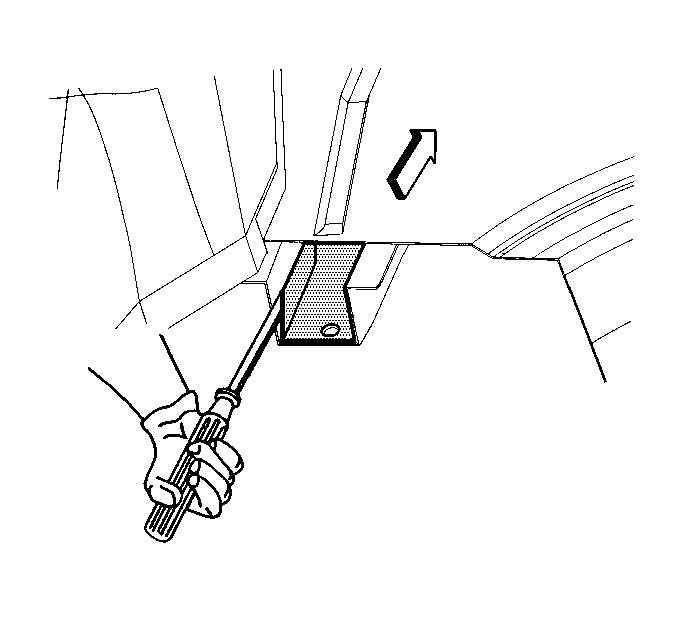
- Secure the rear rail inner reinforcements to the outer panels
between the rough cut and the final cut lines.

- Pry the reinforcements
slightly inward in order to separate the side walls of the inner reinforcement
from the outer panel of the rail.
- Cut the sides of the rail outer panel along the final cut lines
approximately ¾ of the metal thickness deep. Ensure not to damage the
inner reinforcement.
- Bend the rail up and down until the outer panel breaks along the
partial cut.
- Remove the damaged section of the rear rail. Leave the reinforcement
extending from the inside of the remaining rail section.
Preparation Procedure
- Align the templates in the appropriate locations on the service
assembly.
- Use a center punch or an awl in order to mark the assembly by
punching through the templates.
- Remove the templates.
- Connect the dots with a straight edge and scribe the cut lines.
- Connect the left and right floor pan service cut lines around
the forward radius of the spare tire tub. This will ensure the correct overlap
for service assembly installation.
- Drill out the welds at the front edge of the spare tire radius.
- Cut through both of the floor pan and the rails along the floor
pan service cut line.
- Discard the front portion of the assembly.

- Cut through the rails
along the final cut line and remove the excess portions. Do not cut through
the floor pan.
- Drill out the welds that attach the inner reinforcements on the
remaining rail sections to the outer panels (typically 3 welds).
- Remove the inner reinforcements.
- Drill 8 mm (5/16 in) plug weld holes as needed in
the locations indicated from the original floor.
- Drill weld holes along the overlap joint of the floor pan approximately
40 mm (1 ½ in) apart.
Installation Procedure
- Prepare the mating surfaces.
Important: In order to ensure a secure weld, the rear rail sectioning joints should
have a gap of approximately one-and-one-half-times the thickness of the metal.
Trim the parts as necessary to achieve this. Make sure to plug weld the inner
reinforcement of the new rail section. This may require drawing the reinforcement
flat against the rail using a screw. You may need to install backing plates
on either side of the original rails above the reinforcements. These can
be cut from the unused inner reinforcements of the service part. Drill holes
in the rail and plug weld the backing plates in place.

- Inspect for a proper fit
of the rear floor service assembly section. Allow an overlap on
the original floor.
- Plug weld the inner reinforcements to the rail service parts with
the service assembly positioned.

- Verify the service assembly
using body dimensions.
- Plug weld accordingly with frequent measurements in order to ensure
a proper fit.
Important: Use a full-bodied caulk, such as 3M Ultra Pro Sealer P/N 08360-1,
in order to seal both sides of the floor pan seam.
Prior to refinishing, refer to GM 4901 MD-99 Refinish
Manual for recommended products. Do not combine paint systems. Refer to paint
manufacturer's recommendations.
- Clean and prepare the welded surfaces with the following steps:
| 6.1. | Prime with a two-part catalyzed primer. |
| 6.2. | Apply sealers corrosion protection materials as needed. |
| 6.3. | Caulk both sides of the floor pan seam. |
- Reinstall all of the related panels and components.


