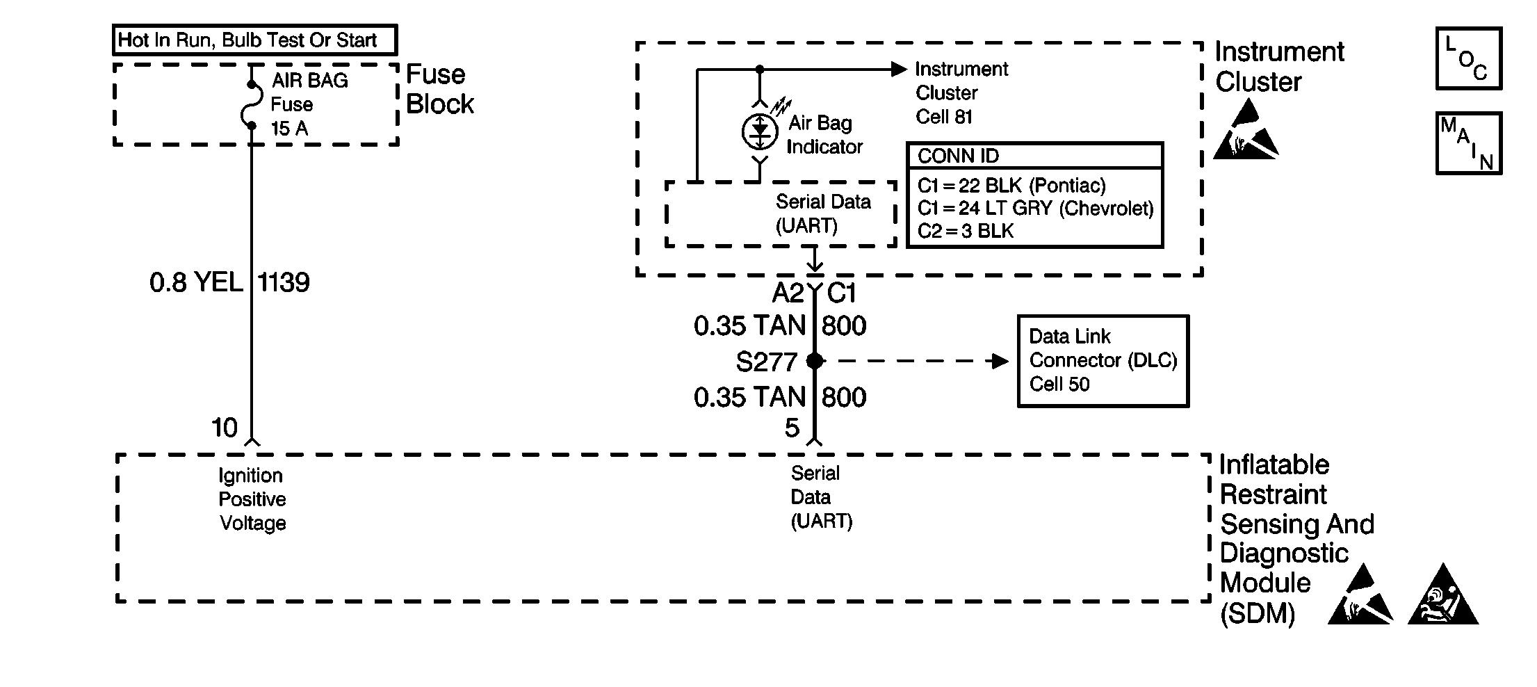
Circuit Description
When the ignition switch is first turned to OFF/UNLOCK or RUN, IGNITION 1 voltage is applied from the CLS/PCM fuse to the INDICATORS bus in the IPC. The ground side of the AIR BAG indicator (LED) is controlled by the instrument cluster microprocessor. When the ignition switch is in the OFF/UNLOCK position, the serial data line (CKT 800) is not operative. This condition will cause the IPC microprocessor to turn the AIR BAG (as well as the SEAT BELT) indicator ON steady. When the ignition switch is first turned to RUN, the AIR BAG fuse applies battery voltage to the IGNITION 1 input, terminal 10. The inflatable restraint Sensing and Diagnostic Module (SDM) responds by flashing the AIR BAG indicator (via the serial data line) seven times.
Conditions for Setting the DTC
| • | The IPC microprocessor sends the SDM five consecutive lamp failure messages or the IPC microprocessor fails to send any message to the SDM for a specified time. |
| • | The CONTINUOUS MONITORING test checks for this DTC. This test occurs when IGNITION 1 is within the normal operating voltage range. |
Action Taken When the DTC Sets
| • | The SDM sets a Diagnostic Trouble Code. |
| • | The SDM attempts to turn ON the AIR BAG warning lamp. |
Conditions for Clearing the MIL/DTC
| • | Current DTC |
| The IPC microprocessor sends the SDM five consecutive lamp functioning properly messages. |
| • | History DTC |
| - | You issue a scan tool CLEAR CODES command. |
| - | Once 250 malfunction free ignition cycles have occurred. |
Diagnostic Aids
Refer to AIR BAG Warning Lamp Comes On Steady to diagnose warning lamp circuit malfunctions.
Step | Action | Value(s) | Yes | No |
|---|---|---|---|---|
1 | Was the SIR Diagnostic System Check performed? | -- | ||
2 |
Is DTC B1061 set? | -- |
