Air Inlet Valve
The valve allows fresh (outside) air to enter the HVAC module when the
air inlet valve is open. The air inlet valve forces recirculation of the air
in the passenger compartment when the air inlet valve closes. The air inlet
valve is located on the top of the HVAC module at the right front corner of
the passenger compartment.
Blower and Evaporator
The blower moves the air in the following manner:
- Across the HVAC module case
- Through the evaporator
The evaporator dehumidifies the air. The resulting moisture expels through
a drain at the front of the dash. The position of the blower speed switch
controls the blower speed. A resistor in the electrical circuit dictates the
blower speed. Refer to
Heater Blower Controls Schematics
for complete wiring information for the A/C electrical system.
Temperature Air Valve and Heater Valve
In all of the A/C modes, the heater core heats the cool dehumidified
air in order to achieve the desired passenger compartment temperature. The
movement of the temperature control knob actuates the temperature valve. The
control knob determines how much heat the incoming air adds. The heater valve
directs the heated air according to the mode setting. The following components
are located in the middle of the HVAC module, downstream of the evaporator:
Mode Air Valve
The mode valve determines the direction of the air mix according to
the input from the mode switch. The mode valve is vacuum actuated. The mode
valve is located in the top of the HVAC module.
Defrost Valve
The defrost valve directs the air mix to the windshield based on the
input from the mode switch. The defrost valve is vacuum actuated. The defrost
valve is located in the top of the HVAC module near the front of the dash.
Ducts and Outlets
A system of ducts and outlets directs the air from the HVAC module to
the passenger compartment. In cases of a poor air output, inspect the following
components for obstructions or other objects:
The objects above may have fallen into the following places:
| • | The air inlet panel screen |
The vehicles are equipped with side window defoggers.
Ventilation

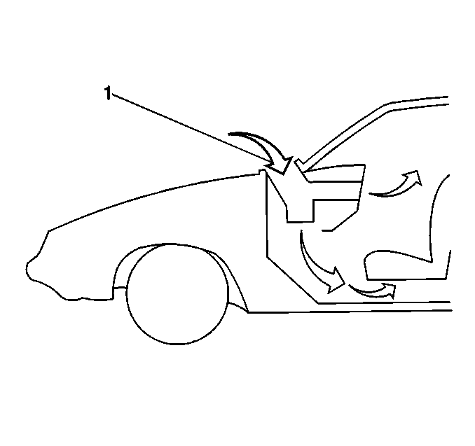
The vehicle has a flow-through
ventilation system. A supply of outside air flows into the vehicle when the
blower motor is running. When the side windows are closed, some air will flow
to the following areas:
- Into the cowl air inlet grille (1)
- Through the vehicle
- Out through the pressure relief valves
Pressure Relief Valve

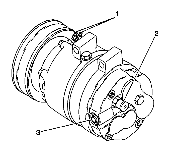
The compressor is equipped
with a pressure relief valve. The pressure relief valve (2) is placed
in the system as a safety factor. Under certain conditions, the refrigerant
on the discharge side may exceed the designed operating pressure. In order
to prevent system damage, engineers designed the valve in order to open automatically
when the high side pressure exceeds a specified amount. Correct the following
conditions that may cause the valve to open:
| • | A defective A/C pressure sensor |
| • | An inoperative cooling fan |
Replace the following items as needed:
Cooling Fan
The cooling fan operation ensures proper operation of the A/C system.
The coolant fan ensures that the proper amount of air flows across the condenser
throughout the vehicle's operating range.
Inspect the fan operation during the A/C diagnosis procedure. Give special
attention to the fan when the following conditions occur:
| • | Excessive high side pressure |
| • | The high side pressure relief valve discharges |
| • | The A/C pressure sensor opens |
The cooling fan control circuits vary according to the following conditions:


