Removal Procedure
- Raise and support the vehicle. Refer to Lifting and Jacking the Vehicle in General Information.
- Clean any dirt or foreign material around the wheel cylinder assembly inlet and pilot.
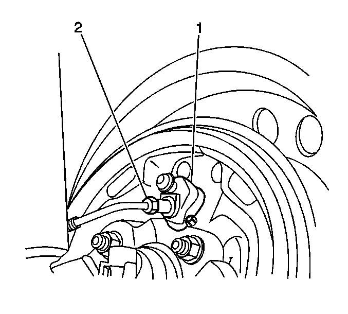
- Remove the brake pipe (2) from the wheel cylinder (1). Plug the opening in the brake pipe to prevent fluid loss and contamination.
- Remove the brake drum. Refer to Brake Drum Replacement .
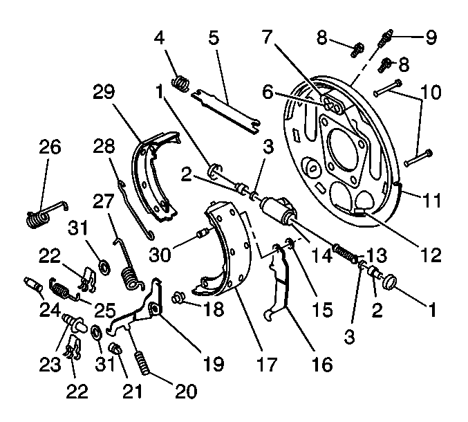
- Remove the brake shoes (17,29). Refer to Brake Shoe Replacement .
- Remove the hub and bearing assembly. Refer to Rear Wheel Bearing and Hub Replacement .
- Pull the backing plate (11) away from the axle flange. Do not let the backing plate hang from the parking brake cable as damage may occur.
- Remove the wheel cylinder bolts (8).
- Remove the wheel cylinder (14).

Caution: When servicing brake parts, do not create dust by grinding or sanding brake linings, by cleaning brake parts with a dry brush or with compressed air. Many earlier models or aftermarket brake parts may contain asbestos fibers which can become airborne if dust is created during servicing. Breathing dust containing asbestos fibers may cause serious bodily harm. A water dampened cloth or water based solution should be used to remove any dust on brake parts. Equipment is commercially available to perform this washing function. These wet methods will prevent fibers from becoming airborne.

Installation Procedure
- Install the wheel cylinder (14).
- Install the wheel cylinder bolts (8).
- Install the backing plate (11) to the axle flange.
- Install the hub and bearing assembly. Refer to Rear Wheel Bearing and Hub Replacement .
- Install the brake shoes (17,29). Refer to Brake Shoe Replacement .
- Install the brake drum. Refer to Brake Drum Replacement .
- Install the brake pipe (2) to the wheel cylinder (1).
- Bleed the wheel cylinder and then the complete brake system. Refer to Hydraulic Brake System Bleeding .

Notice: Use the correct fastener in the correct location. Replacement fasteners must be the correct part number for that application. Fasteners requiring replacement or fasteners requiring the use of thread locking compound or sealant are identified in the service procedure. Do not use paints, lubricants, or corrosion inhibitors on fasteners or fastener joint surfaces unless specified. These coatings affect fastener torque and joint clamping force and may damage the fastener. Use the correct tightening sequence and specifications when installing fasteners in order to avoid damage to parts and systems.
Tighten
Tighten the wheel cylinder bolts to 20 N·m (15 lb ft).

Tighten
Tighten the brake pipe nut to 23 N·m (17 lb ft).
