Removal Procedure
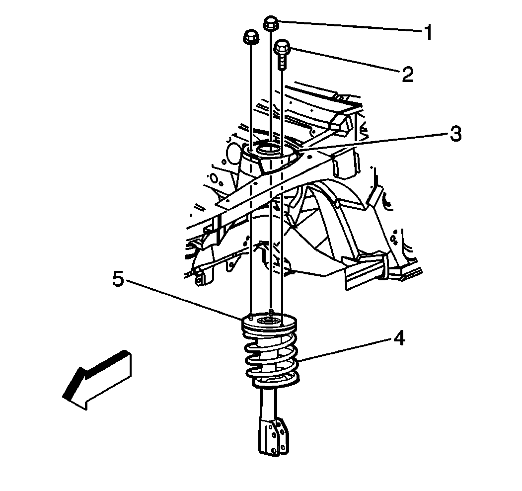
- Remove the nuts (1) and the bolt (2) attaching the top of the strut assembly (5) to the body (3).
- Raise and suitably support the vehicle. Refer to Lifting and Jacking the Vehicle in General Information.
- Place a jackstand under the crossmember.
- Lower the vehicle slightly so that the weight of the vehicle rests on the jack stand and on the control arms.
- Remove the tire and wheel assembly. Refer to Wheel Removal in Tires and Wheels.
- Remove the brake line bracket.
- Scribe the strut flange. Refer to Strut and Knuckle Scribing .
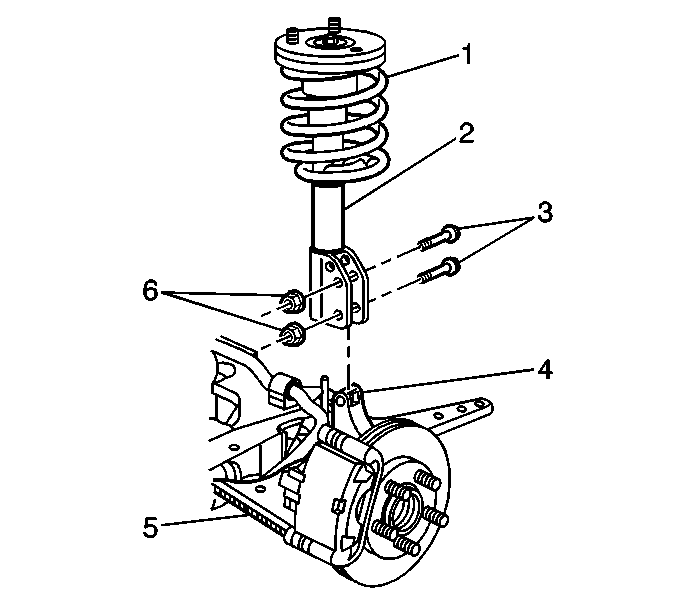
- Remove the bolts (3) and the nuts (6) that attach the strut (2) to the steering knuckle (4).
- Remove the strut assembly (2) from the vehicle.


Important: The steering knuckle must be supported to prevent an axle joint over-extension.
Installation Procedure
- Install the strut assembly (2) to the vehicle.
- Install the bolts (3) and the nuts (6) attaching the strut (2) to the steering knuckle (4).
- Install the brake line bracket.
- Lower the vehicle.
- Install the nuts (1) and the bolt (2) that attach the top of the strut assembly (5) to the body (3).
- Install the tire and wheel assembly. Refer to Wheel Installation in Tires and Wheels.
- Inspect the front wheel alignment. Refer to Wheel Alignment Specifications in Wheel Alignment.

Notice: Use the correct fastener in the correct location. Replacement fasteners must be the correct part number for that application. Fasteners requiring replacement or fasteners requiring the use of thread locking compound or sealant are identified in the service procedure. Do not use paints, lubricants, or corrosion inhibitors on fasteners or fastener joint surfaces unless specified. These coatings affect fastener torque and joint clamping force and may damage the fastener. Use the correct tightening sequence and specifications when installing fasteners in order to avoid damage to parts and systems.
Tighten
Tighten the bolts to 180 N·m (133 lb ft).

Tighten
Tighten the nuts and the bolt to 25 N·m (18 lb ft).
