Removal Procedure
Tools Required
J 28467-360 Engine Support Fixture
- Disconnect the negative battery cable.
- Relieve the fuel system pressure.
- Drain and recover the coolant. Refer to Cooling System Draining and Filling in Engine Cooling.
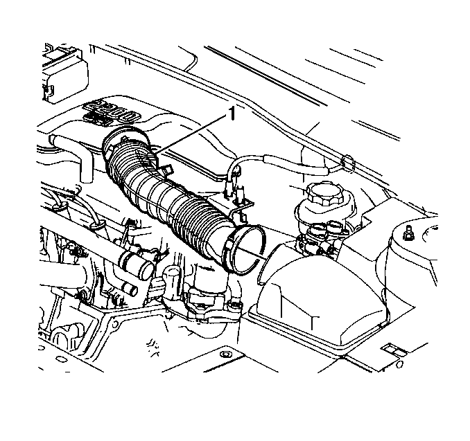
- Remove the air cleaner outlet duct (1).
- Remove the upper radiator hose at the coolant outlet.
- Disconnect the brake booster vacuum hose.
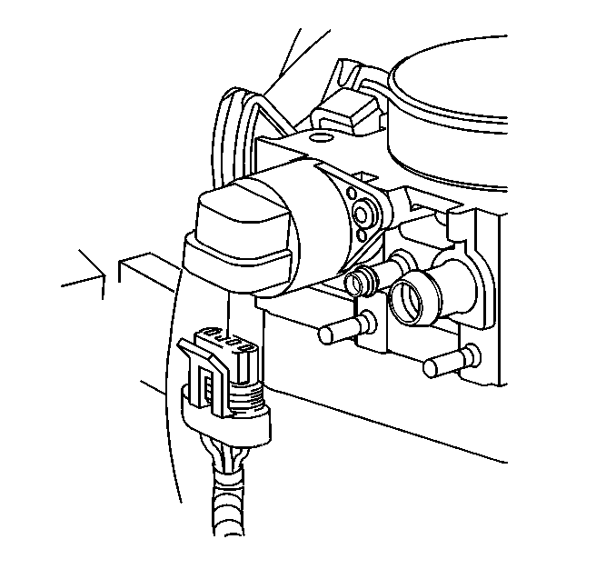
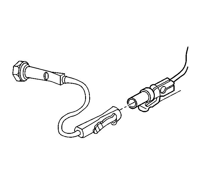
- Disconnect the IAC electrical connection.
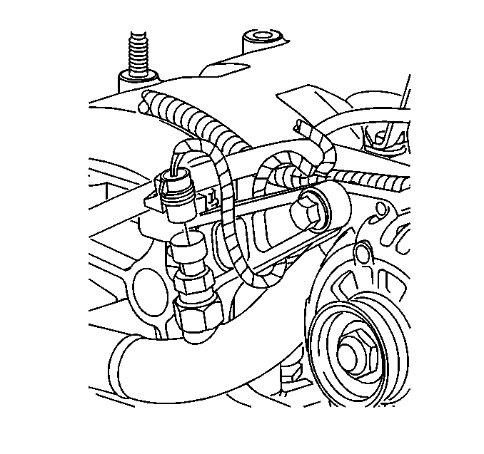
- Disconnect the generator electrical connection.
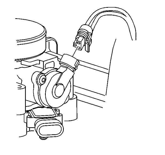
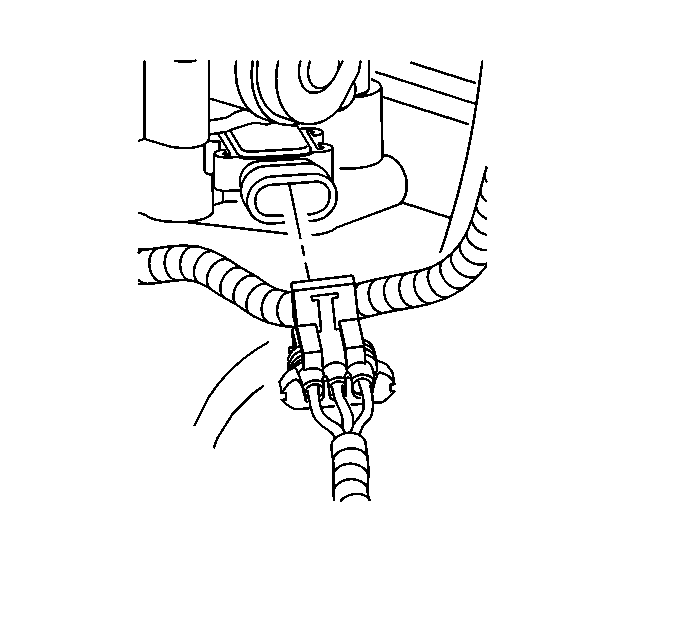
- Disconnect the throttle position (TPS) sensor electrical sensor.
- Disconnect the MAP electrical connection.
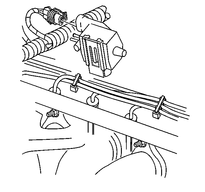
- Disconnect the EVAP emission solenoid electrical connection.
- Disconnect the injector harness electrical connection.
- Disconnect the EGR electrical connection.
- Disconnect the Engine Coolant Temperature (ECT) sensor electrical connection.
- Disconnect the TCC electrical connection.
- Disconnect the Oxygen (02S) sensor electrical connection.
- Disconnect the Park/Neutral position switch.
- Disconnect the engine grounds electrical connection.
- Remove the drive belt. Refer to Drive Belt Replacement .
- Remove the transmission shift control cable from the range select lever and bracket. Refer to Transmission Control Replacement in Automatic Transaxle.
- Remove the coolant surge tank.
- Remove the coolant surge tank hose.
- Disconnect the vacuum line near the master cylinder.
- Install the J 28467-360 .
- Disconnect the lower radiator hose from the coolant pump.
- Raise the vehicle. Refer to Lifting and Jacking the Vehicle in General Information.
- Remove the front tire and wheel assemblies. Refer to Wheel Removal in Tires and Wheels.
- Remove both of the splash shields.
- Remove the exhaust pipe at the exhaust manifold and catalytic converter. Refer to Intermediate Pipe Replacement in Engine Exhaust.
- Remove the engine mount strut.
- Remove the wheel speed sensor wire harness from the control arms.
- Separate the ball joints from the steering knuckles. Refer to Lower Control Arm Ball Joint Replacement in Front Suspension.
- Separate the tie rod ends from the struts. Refer to Rack and Pinion Outer Tie Rod End Replacement in Front Suspension.
- Remove the brake lines from the suspension support.
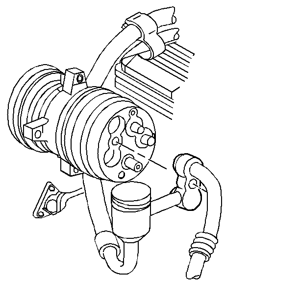
- Remove the A/C compressor and support with the lines attached.
- Disconnect the electronic ignition module electrical connection.
- Disconnect the vehicle speed sensor electrical connections.
- Disconnect the cooling fan electrical connection.
- Disconnect the starter electrical connection.
- Disconnect the A/C compressor electrical connector.
- Disconnect the oil pressure sensor electrical connector.
- Disconnect the oil level sensor electrical connector.
- Disconnect the ground wires.
- Disconnect the power steering lines from the rack and pinion assembly.
- Remove the flexible coupling joint at the rack and pinion assembly.
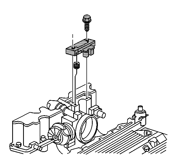
- Remove the following cables from the accelerator control bracket:
- Remove the suspension support assembly. Refer to Front Suspension Support Brace Replacement in Front Suspension.
- Disconnect the heater hoses at the front of the dash.
- Remove both of the drive axles from the transmission and position them aside. Refer to Wheel Drive Shaft Replacement in Wheel Drive Shafts.
- Disconnect the fuel lines.
- Disconnect the transmission cooler lines from the transmission. Refer to Automatic Transmission Oil Cooler Pipes Replacement in Automatic Transaxle - 3T40 or Automatic Transmission Oil Cooler Pipes Replacement in Automatic Transaxle - 4T40-E.
- Remove the transmission mount. Refer to one of the following procedures:
- Remove the engine mount assembly. Refer to Engine Mount Replacement .
- Raise and suitably support the vehicle. Refer to Lifting and Jacking the Vehicle in General Information.
- Lower the vehicle until it rests lightly against the support.
- Remove the J 28467-360 from the engine.
- Raise and suitably support the vehicle. Refer to Lifting and Jacking the Vehicle in General Information. Leave the engine and the transmission assembly on the table.
- Remove the engine from the transmission.
Caution: Unless directed otherwise, the ignition and start switch must be in the OFF or LOCK position, and all electrical loads must be OFF before servicing any electrical component. Disconnect the negative battery cable to prevent an electrical spark should a tool or equipment come in contact with an exposed electrical terminal. Failure to follow these precautions may result in personal injury and/or damage to the vehicle or its components.


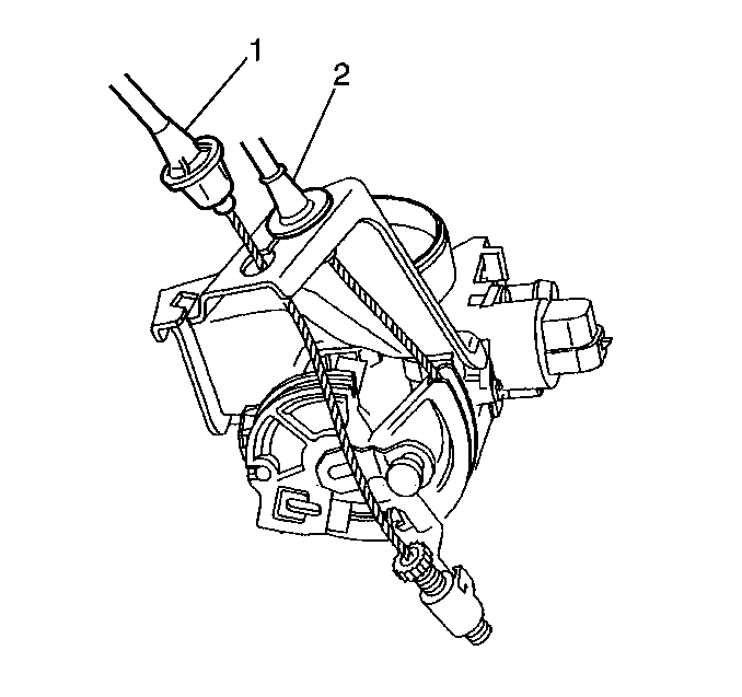
| • | The accelerator control (2). |
| • | The cruise control (1). |
| • | Transmission Mount Replacement in Automatic Transaxle - 3T40 |
| • | Transmission Mount Replacement in Automatic Transaxle - 4T40-E |
Installation Procedure
Tools Required
J 28467-360 Engine Support Fixture
- Install the engine to the transmission.
- Install the transmission bolts.
- Lower the vehicle onto the engine and transmission assembly.
- Install the J 28467-360 .
- Install the engine mount assembly.
- Install the transmission mount. Refer to one of the following procedures:
- Connect the transmission cooler lines to the transmission. Refer to Automatic Transmission Oil Cooler Pipes Replacement in Automatic Transaxle - 3T40 or Automatic Transmission Oil Cooler Pipes Replacement in Automatic Transaxle - 4T40-E.
- Connect the fuel lines. Refer to Fuel Hose/Pipes Replacement - Engine Compartment in Engine Controls.
- Install both of the drive axles. Refer to Wheel Drive Shaft Replacement in Wheel Drive Shafts.
- Connect the heater hoses.
- Install the suspension support assembly. Refer to Front Suspension Support Brace Replacement in Front Suspension.
- Install the following cables to the accelerator control bracket:
- Install the flexible coupling joint to the rack and pinion assembly. Refer to Steering Gear Replacement in Power Steering System.
- Connect the power steering lines. Refer to Power Steering Pressure Pipe/Hose Replacement in Power Steering System.
- Install the electronic ignition module electrical connection.
- Connect the brake lines to the suspension support.
- Connect the vehicle speed sensor electrical connections.
- Connect the cooling fan electrical connection.
- Connect the starter electrical connection.
- Connect the A/C compressor electrical connection.
- Connect the oil pressure sensor electrical connection.
- Connect the oil level sensor electrical connection.
- Connect the grounds electrical connection
- Install the A/C compressor. Refer to Air Conditioning Compressor Replacement in HVAC System - Manual.
- Install the brake lines to the suspension support.
- Install the tie rod ends to the struts. Refer to Rack and Pinion Outer Tie Rod End Replacement in Power Steering System.
- Install the ball joints to the steering knuckles. Refer to Lower Control Arm Ball Joint Replacement in Front Suspension.
- Install the wheel speed sensor wire harness to the control arms.
- Install the engine mount strut.
- Install the exhaust pipe to the exhaust manifold and catalytic converter. Refer to Intermediate Pipe Replacement in Engine Exhaust.
- Install both of the splash shields.
- Install the front tire and wheel assemblies. Refer to Wheel Installation in Tires and Wheels.
- Lower the vehicle.
- Connect the lower radiator hose to the coolant pump.
- Remove the J 28467-360 .
- Connect the vacuum line near the master cylinder.
- Install the coolant surge tank.
- Install the coolant surge tank hose.
- Connect the transmission shift control cable.
- Install the drive belt. Refer to Drive Belt Replacement .
- Install the IAC electrical connection.
- Connect the generator electrical connection.
- Connect the Throttle Position (TPS) sensor electrical connection.
- Connect the MAP electrical connection.
- Connect the EVAP emission solenoid electrical connector.
- Connect the injector harness.
- Connect the EGR electrical connector.
- Connect the Engine Coolant Temperature (ECT) sensor electrical connector.
- Connect the TCC electrical connector.
- Reconnect the Oxygen (02S) sensor.
- Reconnect the Park/Neutral position switch.
- Reconnect the engine ground wires.
- Connect the brake booster vacuum hose.
- Install the upper radiator hose at the coolant outlet.
- Install the air cleaner outlet duct (1).
- Fill the coolant system. Refer to Cooling System Draining and Filling in Engine Cooling.
- Refill the engine with oil.
- Reconnect the negative battery cable.
Notice: Use the correct fastener in the correct location. Replacement fasteners must be the correct part number for that application. Fasteners requiring replacement or fasteners requiring the use of thread locking compound or sealant are identified in the service procedure. Do not use paints, lubricants, or corrosion inhibitors on fasteners or fastener joint surfaces unless specified. These coatings affect fastener torque and joint clamping force and may damage the fastener. Use the correct tightening sequence and specifications when installing fasteners in order to avoid damage to parts and systems.
Tighten
Tighten the bolts to 75 N·m (55 lb ft).
| • | Transmission Mount Replacement in Automatic Transaxle - 3T40 |
| • | Transmission Mount Replacement in Automatic Transaxle - 4T40-E |

| • | The accelerator control (2). |
| • | The cruise control (1) |





Tighten
Tighten the bolt to 16 N·m (12 lb ft).
