FRONT CONVERTER SEAL OIL LEAK INFORMATION/THM 125-C

Some THM 125C transmissions may experience a front oil leak condition which is due to the front converter seal coming out of its seat in the case bore. This condition results from an oil pressure backup behind the converter seal, which causes the converter seal to lose its seat in the case bore.
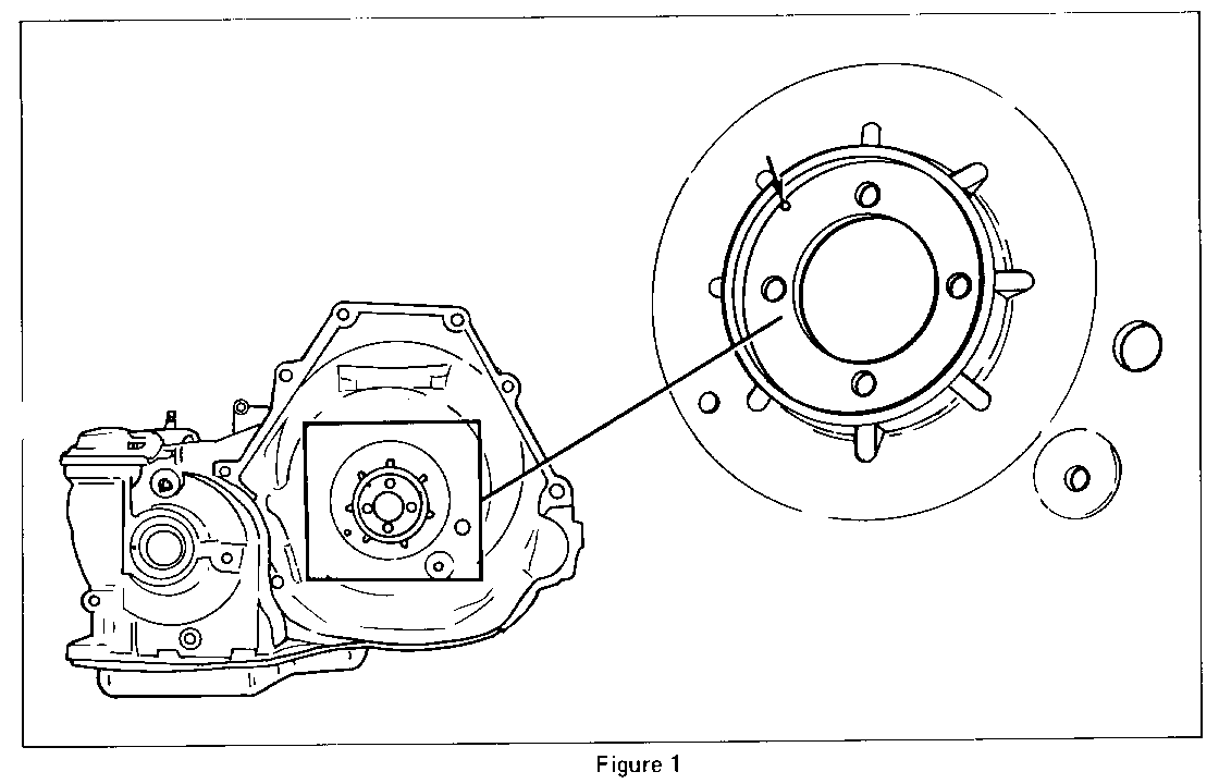
In servicing any THM 125C transmission for this condition, it is recommended that an oil drainback hole be drilled into the converter seal bore of the transmission case (Figure 1).
Proper location is important in drilling the hole. Refer to the following service procedure:
SERVICE PROCEDURE
Always refer to the service manual for the proper removal and installation procedures of component parts.
1. With the converter removed and the transmission in its holding fixture, (Tool #J-28664), remove the valve body cover and gasket (or RTV sealant).
2. Remove the throttle lever and bracket assembly.
3. Disconnect the wire assembly from the electrical connector.
4. Remove the control valve assembly, spacer plate and gaskets. (Use care not to lose the check balls which are loose.)
5. Disconnect the manual valve from the rod and retainer assembly.
6. Remove the transmission case cover.
7. Remove the drive link assembly. (Drive sprocket, driven sprocket, chain, thrust washers and bearings.)
8. Remove the converter oil seal.
9. Remove the drive sprocket support.
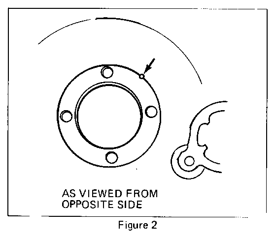
10. Drill, from the seal bore side, a 4.76mm (3/16 in.) minimum diameter hole 2.03mm (.080 in.) inside the radius of the converter seal bore (Figure 1). The hole must be drilled thru so that it exists the other side of the sprocket support mating face, partially outward from the machined surface as shown (Figure 2).
USE CARE NOT TO TOUCH THE SEAL BORE DIAMETER WITH THE DRILL BIT.
11. Clean all aluminum chips from the case. The transmission must be thoroughly cleaned and all burrs removed from the drilled hole before reassembly.
12. Install the drive sprocket support and torque the four torx head bolts to 24 N.m (18 ft. lbs.).
13. Install a new converter oil seal (P/N 8637906 for a 245mm converter or P/N 8631950 for a 254mm converter) into the case. Use tool #J-28540.
14. Install the drive link assembly.
15. Install the transmission case cover. Torque all bolts to 24 N.m (18 ft. lbs.).
16. Connect the rod and retainer assembly to the manual valve.
17. Install the control valve assembly, spacer plate and gaskets, placing the check balls in their proper locations. Torque all valve body to case cover attaching bolts to 11 N.m (8 ft. lbs.), and all valve body to case attaching bolts to 24 N.m (18 ft. lbs.).
18. Connect the wire assembly to the electrical connector.
19. Install the throttle lever and bracket assembly.
20. Install the valve body cover and gasket (or RTV sealant). Torque all bolts to 16 N.m (12 ft. lbs.).


General Motors bulletins are intended for use by professional technicians, not a "do-it-yourselfer". They are written to inform those technicians of conditions that may occur on some vehicles, or to provide information that could assist in the proper service of a vehicle. Properly trained technicians have the equipment, tools, safety instructions and know-how to do a job properly and safely. If a condition is described, do not assume that the bulletin applies to your vehicle, or that your vehicle will have that condition. See a General Motors dealer servicing your brand of General Motors vehicle for information on whether your vehicle may benefit from the information.
