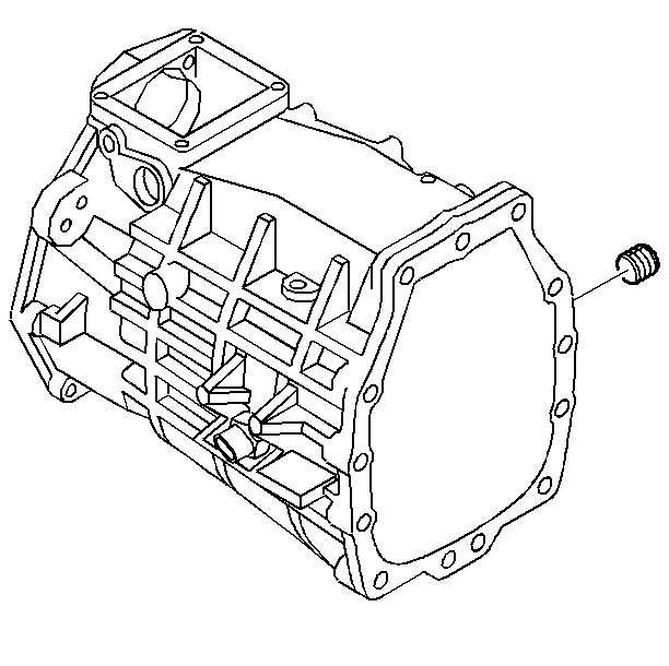
- Install the 1st/2nd and
the 3rd/4th shift shaft bushings. Use the J 36190
, the J 39439-4
, and the J 39439-3
.

- Install the mainshaft
bearing race, using the J 8092
and the J 39435
.

- Install the countershaft
bearing race, using the J 8092
and the J 39435
.

- Install the dowel pins.

- Apply sealant GM P/N United
States 12346004, GM P/N Canada 10953480 or equivalent
to the threads of the reverse lamp switch.

Notice: Use the correct fastener in the correct location. Replacement fasteners
must be the correct part number for that application. Fasteners requiring
replacement or fasteners requiring the use of thread locking compound or sealant
are identified in the service procedure. Do not use paints, lubricants, or
corrosion inhibitors on fasteners or fastener joint surfaces unless specified.
These coatings affect fastener torque and joint clamping force and may damage
the fastener. Use the correct tightening sequence and specifications when
installing fasteners in order to avoid damage to parts and systems.
- Install the reverse lamp switch.
Tighten
Tighten the switch to 27 N·m (20 lb ft).

- Apply sealant GM P/N United
States 12346004, GM P/N Canada 10953480 or equivalent
to the transmission case fill plug threads.

- Install the transmission
case fill plug.
Tighten
Tighten the oil fill plug to 18 N·m (13 lb ft).

Notice: The H-pattern on the guide plate must face the extension housing. If
the guide plate is installed incorrectly, then damage will occur.
- Install the guide plate and the guide plate bolts.
Tighten
Tighten the bolts to 22 N·m (16 Ib ft).


