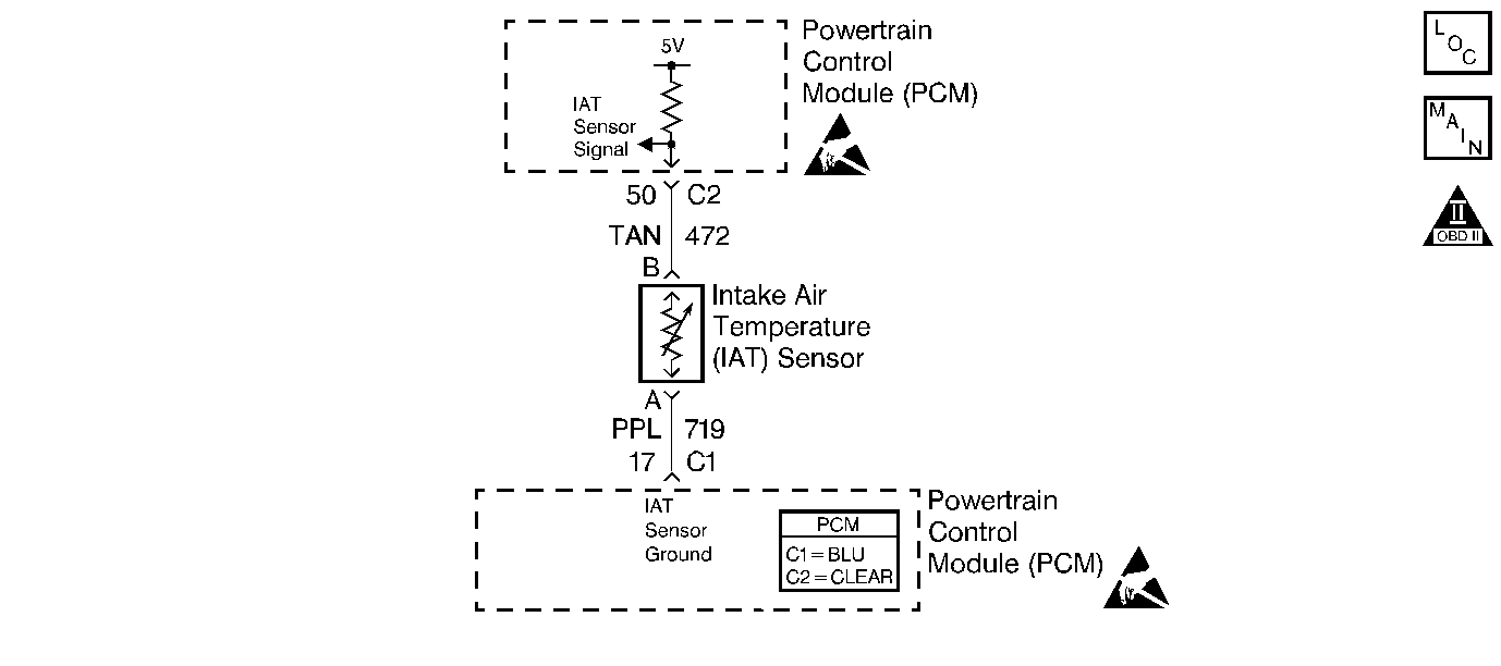
Circuit Description
The intake air temperature (IAT) sensor is a thermistor which measures
the temperature of the air entering the engine. The PCM applies 5.0V through
a pull up resistor. When the intake air is cold, the sensor resistance
is high and the PCM will monitor a high signal voltage on the IAT sensor
signal circuit. As the intake air warm, the sensor resistance becomes
lower causing the PCM to monitor a lower voltage. If the PCM detects
an excessively high IAT sensor signal voltage (low temperature indicated),
DTC P0113 will set.
Conditions for Running The DTC
| • | No active ECT sensor or VSS DTCs present. |
| • | The engine has been running for more than 3 minutes. |
| • | Vehicle speed is less than 8km/h (5mph). |
| • | Mass air flow is less than 8 gm/s. |
| • | Engine coolant temperature is more than 60°C (140°F). |
Conditions for Setting the DTC
IAT signal voltage indicates an intake air temperature less than -38°C
(-36°F).
Action Taken When the DTC Sets
| • | The PCM will illuminate the malfunction indicator lamp (MIL) during
the second consecutive trip in which the diagnostic test has been run and
failed. |
| • | The PCM will store conditions which were present when the DTC
set as Freeze Frame/Failure Records data. |
Conditions for Clearing the MIL/DTC
| • | The PCM will turn OFF the malfunction indicator lamp (MIL) during
the third consecutive trip in which the diagnostic has run and
passed. |
| • | The history DTC will clear after 40 consecutive warm-up
cycles have occurred without a malfunction. |
| • | The DTC can be cleared by using a scan tool. |
Diagnostic Aids
Inspect for the following:
Many situations may lead to an intermittent condition. Perform each inspection
or test as directed.
Important: : Remove any debris from the connector surfaces
before servicing a component. Inspect the connector gaskets when diagnosing or replacing
a component. Ensure that the gaskets are installed correctly. The gaskets prevent
contaminate intrusion.
| • | Loose terminal connection |
| • | Damaged harness--Inspect the wiring harness for damage. If the harness
inspection does not reveal a problem, observe the display on the scan tool while
moving connectors and wiring harnesses related to the sensor. A change in the scan
tool display may indicate the location of the fault. Refer to
Wiring Repairs
in Wiring Systems for diagnosis and repair. |
| • | Inspect the powertrain control module (PCM) and the engine grounds for
clean and secure connections. Refer to
Wiring Repairs
in Wiring Systems for diagnosis and repair. |
If the condition is determined to be intermittent, reviewing the Snapshot
or Freeze Frame/Failure Records may be useful in determining when the DTC or condition
was identified.

