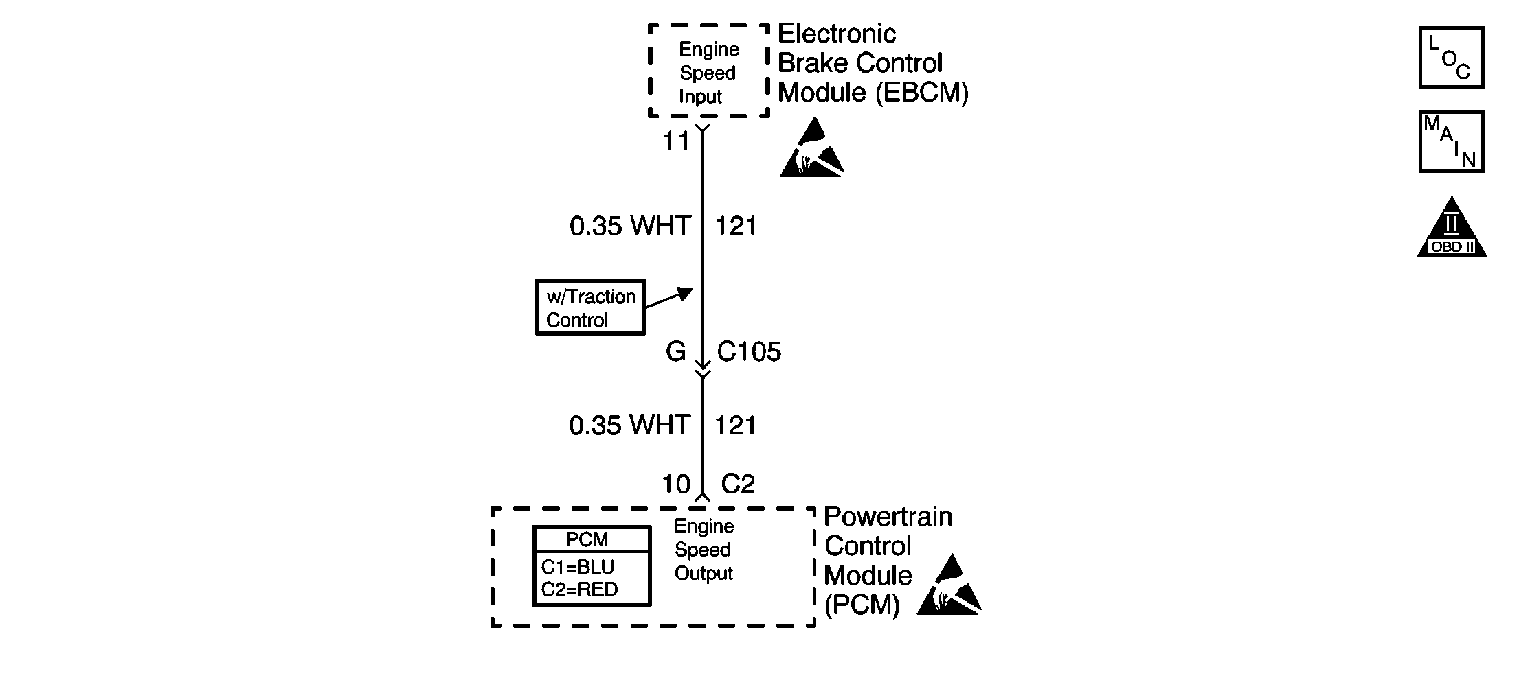
Circuit Description
The PCM creates the Engine Speed Output signal by rapidly grounding this circuit via an internal switch called a driver.
The driver supplies the ground for the component being controlled. Each driver has a fault line which the PCM monitors. When the PCM commands a component ON, the voltage of the control circuit should be low (near 0 volts). When the PCM commands the control circuit to a component OFF, the voltage potential of the circuit should be high (near battery voltage).
Diagnostic Aids
Important:
• Remove any debris from the PCM connector surfaces before servicing
the PCM. Inspect the PCM connector gaskets when diagnosing/replacing the PCM.
Ensure that the gaskets are installed correctly. The gaskets prevent
water intrusion into the PCM. • For any test that requires probing the PCM or component harness
connectors, use the Connector Test Adapter Kit J 35616
. Using this kit prevents any damage to the harness
connector terminals. Refer to
Using Connector Test Adapters
in Wiring Systems.
For an intermittent, refer to Symptoms .
Test Description
The numbers below refer to the step numbers on the diagnostic table.
-
This step is verifying a voltage from the Instrument Cluster.
-
This step is testing for a short to ground.
Step | Action | Value(s) | Yes | No |
|---|---|---|---|---|
1 | Did you perform the Powertrain On-Board Diagnostic (OBD) System Check? | -- | ||
2 |
Important: If the I/P is completely inoperative, refer to Diagnostic System Check - Instrument Cluster in Instrument Panel, Gauges and Console. With the engine running, does the vehicles tachometer indicate engine RPM? | -- | Go to Diagnostic Aids | |
Does the DMM display the specified value? | B+ | |||
4 |
Does the DMM display continuity? | -- | ||
Test the continuity of the engine speed circuit using the DMM J 39200 . Refer to Testing for Continuity in Wiring Systems. Does the DMM display continuity? | -- | Go to Diagnostic System Check - Instrument Cluster in Instrument Panel Gauges and Console. | ||
6 | Repair the engine speed circuit for an open or a short to ground. Refer to Wiring Repairs in Wiring Systems. Is the action complete? | -- | -- | |
7 |
Did you find and correct the condition? | -- | ||
8 |
Important: Program the replacement PCM. Refer to Powertrain Control Module Replacement/Programming Replace the PCM. Is the action complete? | -- | -- | |
9 | Select the Capture Info option and the Review Info option using the scan tool. Does the scan tool display any DTCs that you have not diagnosed? | -- | Go to the applicable DTC table | System OK |
