Removal Procedure
- Raise and suitably support the vehicle. Refer to Lifting and Jacking the Vehicle in General Information.
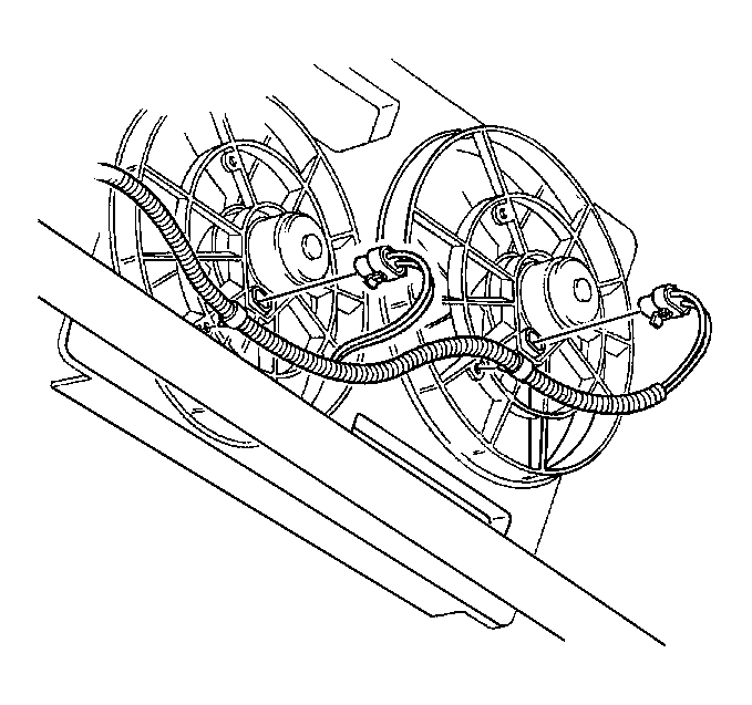
- Remove the electrical connectors from the fan shroud.
- Drain the cooling system. Refer to Cooling System Draining and Filling in Engine Cooling.
- Drain the engine oil.
- Lower the vehicle.
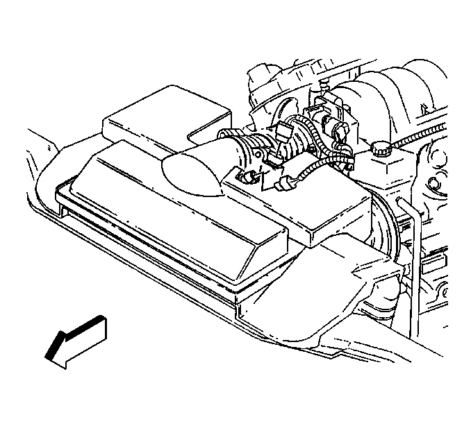
- Disconnect the intake air temperature (IAT) sensor electrical connector at the intake duct.
- Disconnect the mass airflow (MAF) sensor electrical connector at the intake duct.
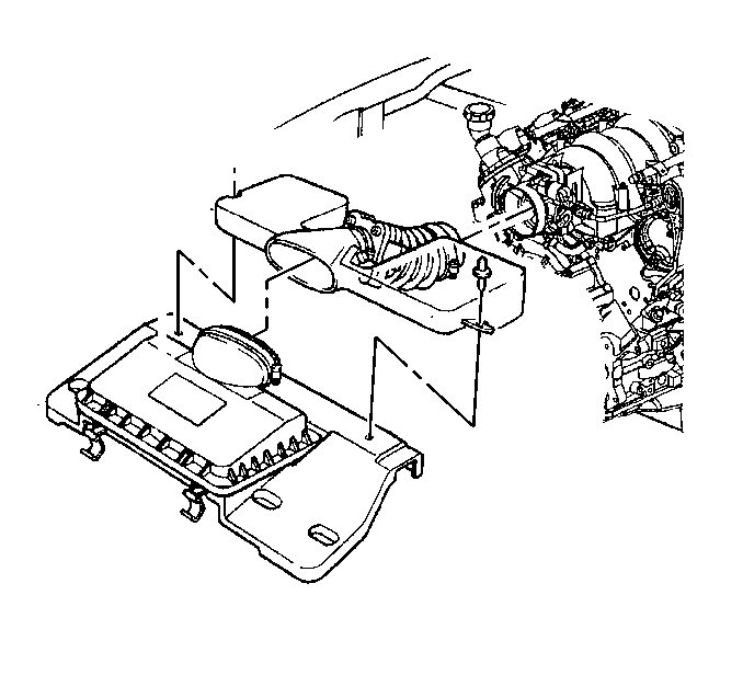
- Remove the air intake duct.
- Remove the air conditioning (A/C) drive belt. Refer to Drive Belt Replacement .
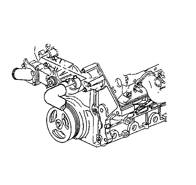
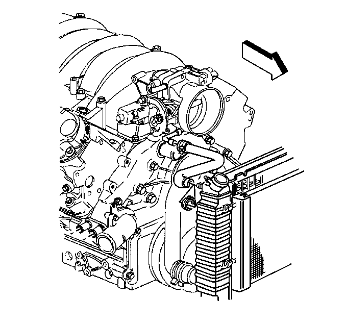
- Remove the upper radiator hose from the water pump.
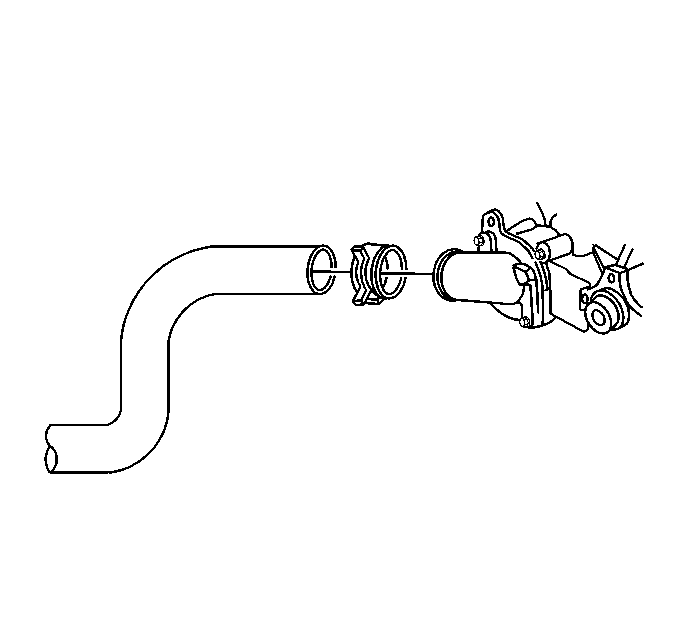
- Remove the radiator hose from the water intlet housing.
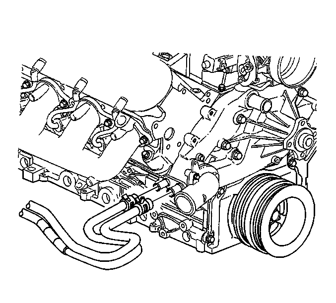
- Remove the two heater hoses from the water pump.
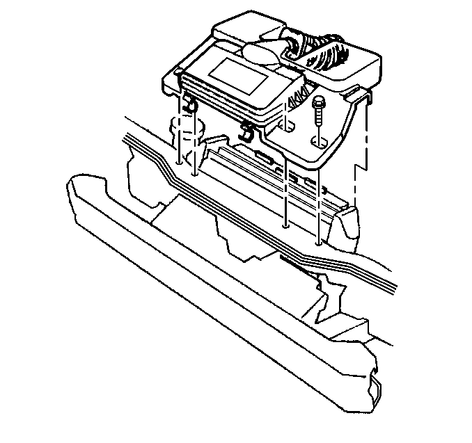
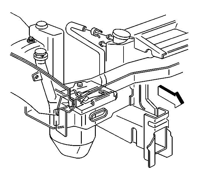
- Remove the upper radiator support.
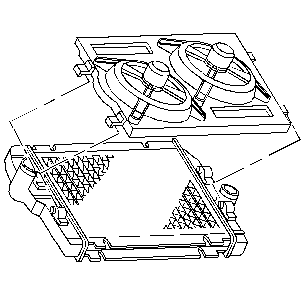
- Remove the fan shroud.
- Remove the drive belt tensioner. Refer to Drive Belt Tensioner Replacement .
- Remove the overflow hose from the radiator.
- Remove the throttle body heater hose from the radiator.
- Remove the drive belt idler pulley. Refer to Drive Belt Idler Pulley Replacement .
- Remove the water pump. Refer to Water Pump Replacement in Engine Cooling.
- Raise and suitably support the vehicle. Refer to Lifting and Jacking the Vehicle in General Information.
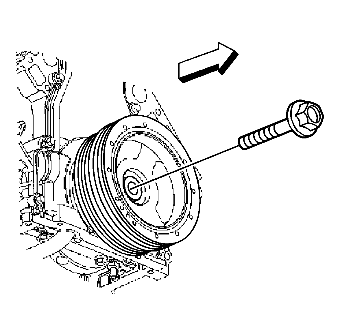
- Remove the crankshaft balancer. Refer to Crankshaft Balancer Replacement .
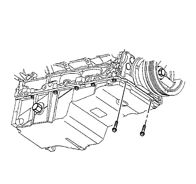
- Remove the oil pan-to-front cover bolts.
- Remove the engine front cover bolts.
- Remove the front cover and gasket.
- Remove the crankshaft oil seal from the cover.
- Inspect for the following:
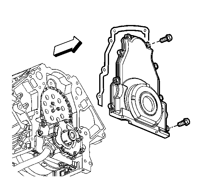
| • | Gasket sealing surfaces fro excessive scratches or gouging. |
| • | Cover-to-oil pan threaded bolt holes for damaged threads or debris. |
| • | Crankshaft oil seal mounting bore for damage. |
| • | Oil pan gasket for damage. |
Installation Procedure
Tools Required
J 41476 Front and Rear Cover Alignment (Crankshaft Oil Seal Area)
- Apply a 5 mm (0.20 in) bead of sealant GM P/N 12378190 or equivalent 20 mm (0.80 in) long to the oil pan to engine block junction.
- Install a new crankshaft oil seal to the front cover.
- Install the front cover gasket and cover.
- Install the front cover bolts finger tight. Do not overtighten.
- Install the J 41476 .
- Remove the J 41476 .
- Install the crankshaft balancer. Refer to Crankshaft Balancer Replacement .
- Lower the vehicle.
- Install the water pump. Refer to Water Pump Replacement in Engine Cooling.
- Install the drive belt idler pulley. Refer to Drive Belt Idler Pulley Replacement .
- Install the throttle body heater hose to the radiator.
- Install the overflow hose to the radiator.
- Install the drive belt tensioner. Refer to Drive Belt Tensioner Replacement .
- Install the fan shroud.
- Install the upper radiator support.
- Install the lower radiator hose to the water inlet housing.
- Install the upper radiator hose to the water pump.
- Install the A/C drive belt. Refer to Drive Belt Replacement .
- Install the two heater hoses to the water pump.
- Install the air intake duct.
- Connect the MAF sensor electrical connector at the intake duct.
- Connect the IAT sensor electrical connector at the intake duct.
- Refill the engine oil.
- Refill the cooling system. Refer to Cooling System Draining and Filling in Engine Cooling.
- Install the electrical connectors to the fan shroud.
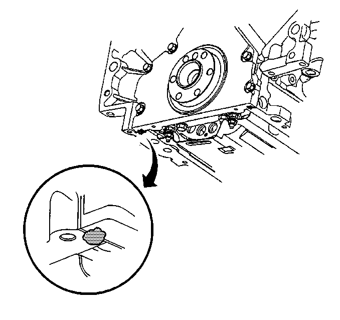
Important:
• Do not reuse the crankshaft oil seal or the engine front cover
gasket. • All gasket surfaces should be free of oil or other foreign material
during assembly. • The crankshaft front oil seal MUST be centered in relation to
the crankshaft.

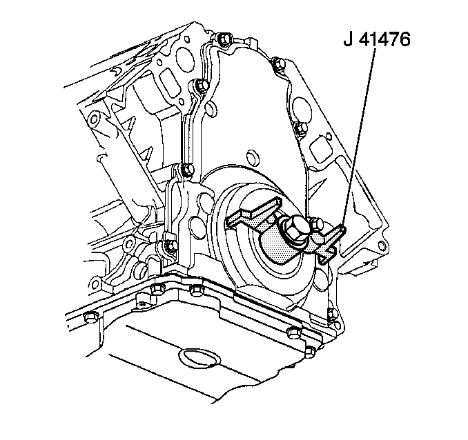
Important: Align the tapered legs of the J 41476 with the machined alignment surfaces on the front cover.
Notice: Use the correct fastener in the correct location. Replacement fasteners must be the correct part number for that application. Fasteners requiring replacement or fasteners requiring the use of thread locking compound or sealant are identified in the service procedure. Do not use paints, lubricants, or corrosion inhibitors on fasteners or fastener joint surfaces unless specified. These coatings affect fastener torque and joint clamping force and may damage the fastener. Use the correct tightening sequence and specifications when installing fasteners in order to avoid damage to parts and systems.
Tighten
| • | Tighten the oil pan-to-front cover bolts to 25 N·m (18 lb ft). |
| • | Tighten the engine front cover bolts to to 25 N·m (18 lb ft). |


Tighten
Tighten the radiator support/air cleaner bolts to 12 N·m
(106 lb in).


