Removal Procedure
- Remove the necessary coolant from the radiator. Refer to Cooling System Draining and Filling .
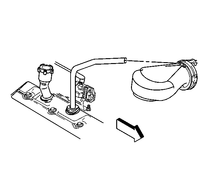
- Disconnect the breather tube at the air cleaner outlet duct.
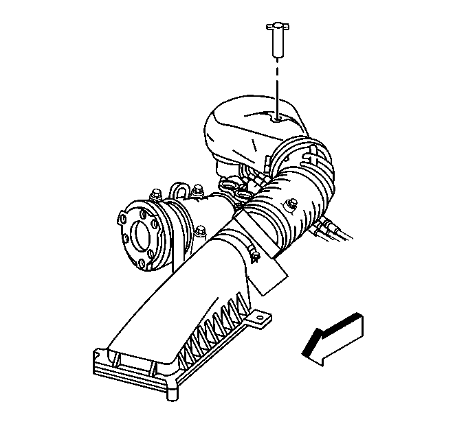
- Remove the air cleaner outlet duct retaining wingnut.
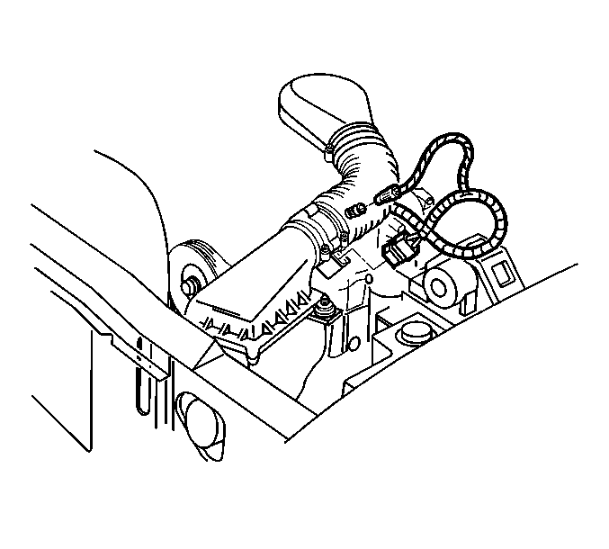
- Disconnect the IAT sensor harness connector.
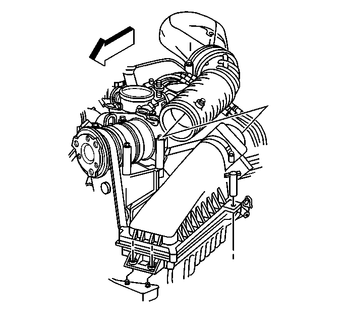
- Remove the air cleaner outlet duct from the throttle body.
- Remove the throttle body bracket. Refer to Throttle Body Assembly Replacement in Engine Controls - 4.3L.
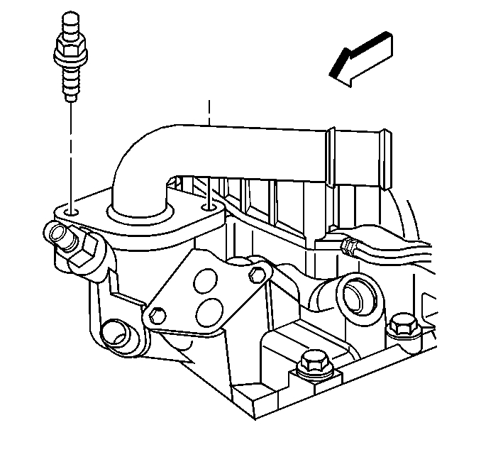
- Remove the thermostat housing mounting bolts.
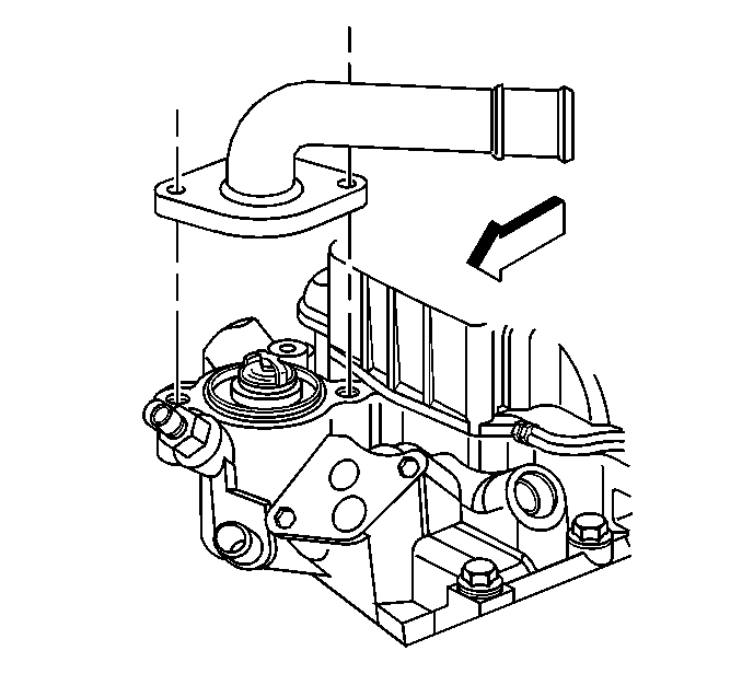
- Remove the thermostat housing from the lower intake manifold and set aside.
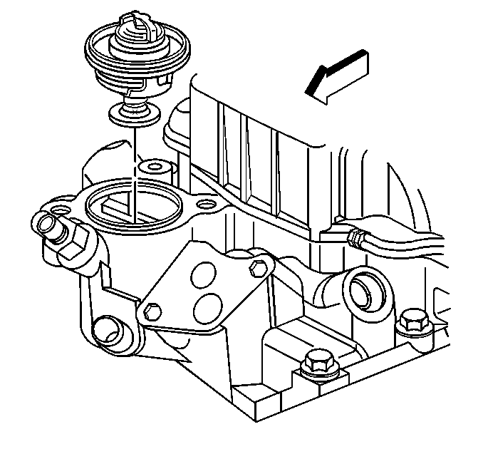
- Remove the gasket or O-ring.
- Remove the coolant thermostat.
- Clean all the sealing surfaces of the coolant outlet.
- Clean the sealing surface on the lower intake manifold.
Installation Procedure
- Install the coolant thermostat.
- Install a new gasket or O-ring.
- Place the thermostat housing on the lower intake manifold. Ensure the gasket or O-ring is in correct position.
- Install the thermostat housing mounting bolts.
- Install the throttle body bracket. Refer to Throttle Body Assembly Replacement in Engine Controls - 4.3L.
- Fill the cooling system with specified coolant and concentration. Refer to Cooling System Draining and Filling .
- Install air cleaner outlet duct to throttle body.
- Install air cleaner outlet duct to MAF sensor.
- Connect the IAT sensor harness connector.
- Install the air cleaner outlet duct retaining wingnut.
- Connect the breather tube to the air cleaner outlet duct.
- Inspect all sealing surfaces for leaks after starting the engine.

Important: In order to prevent leakage, thoroughly clean all parts and sealing surfaces.


Notice: Use the correct fastener in the correct location. Replacement fasteners must be the correct part number for that application. Fasteners requiring replacement or fasteners requiring the use of thread locking compound or sealant are identified in the service procedure. Do not use paints, lubricants, or corrosion inhibitors on fasteners or fastener joint surfaces unless specified. These coatings affect fastener torque and joint clamping force and may damage the fastener. Use the correct tightening sequence and specifications when installing fasteners in order to avoid damage to parts and systems.
Tighten
Tighten thermostat housing mounting bolts to 19 N·m (14 lb ft).
Notice:
• Handle the MAF sensor carefully. • Do not drop the MAF sensor in order to prevent damage to the MAF
sensor. • Do not damage the screen located on the air inlet
end of the MAF. • Do not touch the sensing elements. • Do not allow solvents and lubricants to come in contact with the
sensing elements. • Use a small amount of a soap based solution in order to aid in
the installation.

Tighten
Tighten the hose clamp to 4 N·m (32 lb in).


Tighten
Tighten the wingnut to 2 N·m (18 lb in).

