Removal Procedure
- Remove the battery and the battery tray. Refer to
Battery Tray Replacement
in Engine Electrical.
- Remove the right side wheel drive shaft. Refer to
Wheel Drive Shaft Replacement
in Wheel Drive Shafts.
- Remove the wire from the indicator switch.
- Remove the cable housing and the shift spring.

- Remove the bolts, the
nuts, and the washers from the axle tube.
- Remove the remaining two axle shaft upper bolts.
Important: Do not allow the following components to fall out of the carrier assembly
or become damaged:
| • | The shift fork assembly |
- Remove the axle shaft and tube by working the shaft and tube around
the drive axle.
Disassembly Procedure
Tools Required
- Remove the axle shaft.
| 1.1. | Hold the tube in a vise by the mounting flange. |
| 1.2. | Tap out the shaft using a soft mallet. |
- Remove the shaft deflector.
- Remove the shaft seal using a seal removal tool.
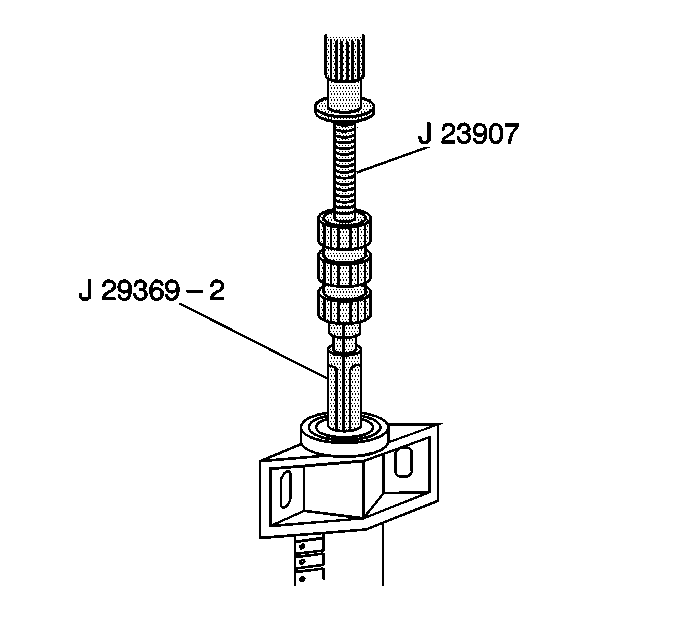
- Remove the bearing using
the J 29369-2
and the J 23907
.
- Remove the shift cable housing seal. Drive out the seal using
a punch.
- Remove the retaining ring and the output shaft.
Assembly Procedure
Tools Required
| • | J 33799 Shift
Cable Housing Seal Installer |
| • | J 33844 Axle
Tube Bearing Installer |
- Install the output shaft and the retaining ring.
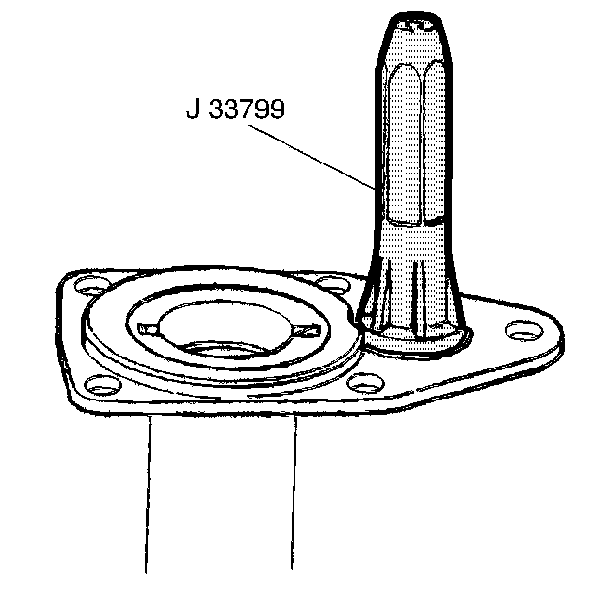
- Install the shaft seal
using the J 33799
.
- Install the shaft bearing using the J 33844
.
The bearing is installed to the proper depth when the tool is flush
with the tube end.
- Lubricate the bearing using axle lubricant. Refer to
Fluid and Lubricant Recommendations
in Maintenance
and Lubrication.
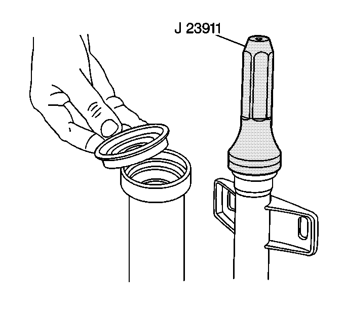
- Install the seal with
the J 23911
. Drive in
the seal until the seal flange is flush with the tube end.
- Install the axle shaft.
- Clean the sealing surfaces of the tube and carrier assembly using
a suitable solvent.
Installation Procedure
Tools Required
J 33798 Hub Engagement
Tool
- Apply a bead of sealer (GM P/N 12345739 or equivalent)
to the carrier sealing surface.
- Ensure that the following components are in place in the carrier
assembly:
| • | The shift fork assembly |
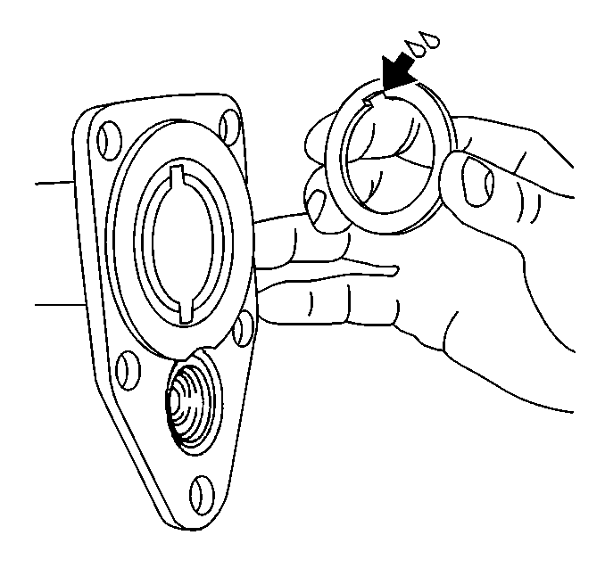
- Install the thrust washer
to the tube as shown. Use grease in order to hold the washer in place.
- Install the shaft and tube assembly to the carrier.
- Install the shaft tube bolt at the 1 o'clock position.
Tighten the bolt finger tight.
- Pull the shaft and tube assembly down in order to install the
remaining bolts.

Notice: Use the correct fastener in the correct location. Replacement fasteners
must be the correct part number for that application. Fasteners requiring
replacement or fasteners requiring the use of thread locking compound or sealant
are identified in the service procedure. Do not use paints, lubricants, or
corrosion inhibitors on fasteners or fastener joint surfaces unless specified.
These coatings affect fastener torque and joint clamping force and may damage
the fastener. Use the correct tightening sequence and specifications when
installing fasteners in order to avoid damage to parts and systems.
- Install the bolts,
the washers, and the nuts.
Tighten
Tighten the nuts to 98 N·m (72 lb ft).
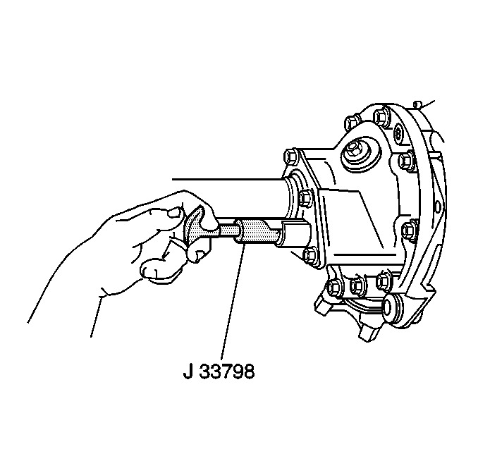
- Inspect the operation
of the shift mechanism. Use the J 33798
. Insert the tool into the shift fork. Inspect for
rotation of the axle shaft.
- Connect the wire to the shift indicator switch.
- Install the right side wheel drive axle. Refer to
Wheel Drive Shaft Replacement
in Wheel Drive Shafts.
- Inspect the axle lubricant level. Add lubricant as necessary.
Refer to
Lubrication Specifications
.
- Lower the vehicle.
- Install the battery and the battery tray. Refer to
Battery Tray Replacement
in Engine Electrical.


