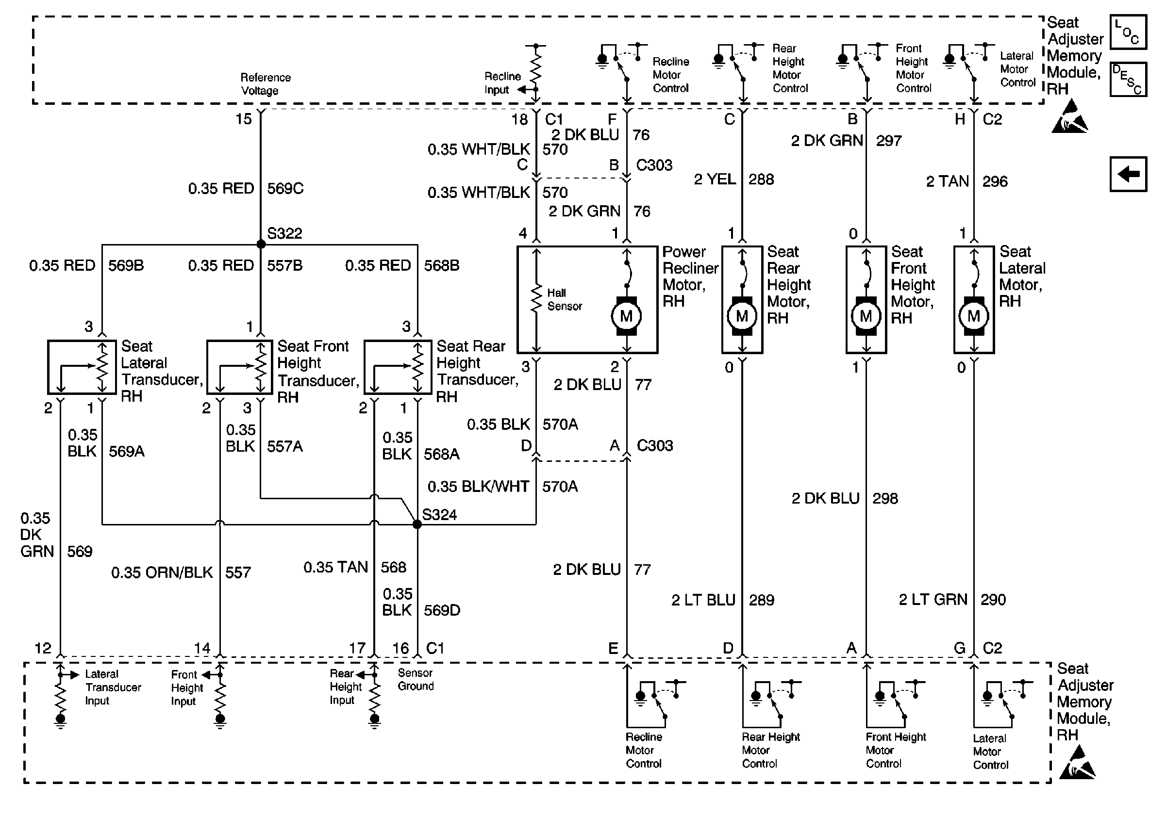
For wiring diagrams, refer to
Seat Adjuster Memory Module, Transducers and Motors

.
Circuit Description
The seat adjuster memory module monitors the seat lateral motor position through the seat lateral transducer CKT 569 (DK GRN). The seat adjuster memory module also sends a reference voltage on CKT 569 (RED) to CKT 569B (RED) and provides a sensor ground, CKT 569 (BLK) to CKT 569A (BLK).
Conditions for Setting the DTC
The DTC will set if the seat adjuster memory module detects that the seat rear height sensor output voltage is either too high or too low due to the following:
| • | An open circuit |
| • | A short to ground |
| • | A short to power |
| • | A defective seat height transducer |
Conditions for Clearing the DTC
| • | A history DTC will clear after 100 consecutive fault free ignition cycles. |
| • | Use a scan tool in order to clear history and current DTCs. |
Diagnostic Aids
One or more of the following conditions could be the cause of an intermittent failure:
| • | A poor connection |
| • | A break in the wire insulation that exposes the internal wire |
| • | A wire broken inside the insulation |
Test Description
The numbers below refer to the step numbers on the diagnostic table.
-
This step inspects for current DTCs.
-
This step locates and repairs open(s) in the wiring between the seat lateral transducer and the seat adjuster memory module.
-
This step locates and repairs short(s) to ground in the wiring between the seat lateral transducer and the seat adjuster memory module.
-
This step verifies that the seat adjuster memory module is supplying the reference voltage to the seat lateral transducer.
-
This step replaces a defective seat lateral transducer.
-
This step replaces a defective seat adjuster memory module.
Step | Action | Value(s) | Yes | No | ||||||||
|---|---|---|---|---|---|---|---|---|---|---|---|---|
1 | Did you perform the Power Seat Systems Diagnostic System Check? | -- | Go to Step 2 | |||||||||
Does DTC B2376 reset? | -- | Go to Step 3 | ||||||||||
Refer to Circuit Testing and Wiring Repairs in wiring systems. Did you find and correct the condition? | -- | Go to Step 4 | ||||||||||
Refer to Circuit Testing and Wiring Repairs in wiring systems. Did you find and correct the condition? | -- | Go to Step 5 | ||||||||||
Refer to Circuit Testing in wiring systems. Does the voltage equal the specified value? | 5 V | Go to Step 6 | Go to Step 7 | |||||||||
Replace the seat lateral transducer. Refer to Front Seat Adjuster Replacement . Is the repair complete? | -- | -- | ||||||||||
Replace the seat adjuster memory module. Refer to Memory Seat Control Module Replacement . Is the repair complete? | -- | -- |
