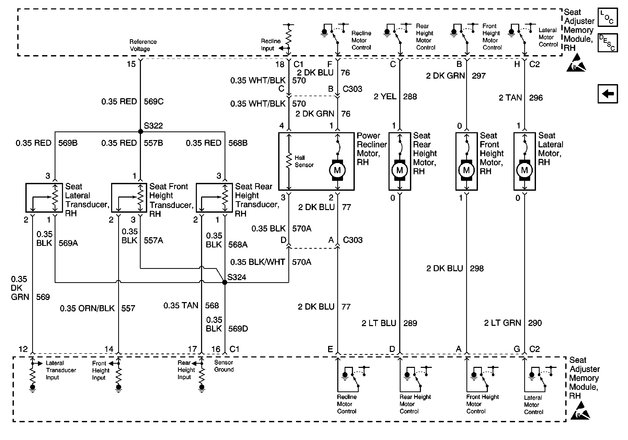
For wiring diagrams, refer to
Seat Adjuster Memory Module, Transducers and Motors

.
Circuit Description
The seat adjuster memory module controls the seat recliner motor power and ground through CKT 276 (LT GRN) and CKT 277 (LT BLU). The seat adjuster memory module also senses the seat recliner motor position through a hall sensor within the motor through CKT 570 (WHT/BLK) while utilizing CKT 570A (BLK) as a sensor ground.
Conditions for Setting the DTC
The DTC will set if the seat adjuster memory module detects through the hall sensor that the recline motor is not responding to the seat adjuster memory module commands due to the following:
| • | An open circuit |
| • | A short to ground |
| • | A short to power |
| • | An inoperative motor |
Conditions for Clearing the DTC
| • | A history DTC will clear after 100 consecutive fault free ignition cycles. |
| • | Use a scan tool in order to clear history and current DTCs. |
Diagnostic Aids
One or more of the following conditions could be the cause of an intermittent failure:
| • | A poor connection |
| • | A break in the wire insulation that exposes the internal wire |
| • | A wire broken inside the insulation |
Test Description
The numbers below refer to the step numbers on the diagnostic table.
-
This step inspects for current DTCs.
-
This step locates and repairs open(s) in the wiring between the seat recliner motor and the seat adjuster memory module.
-
This step locates and repairs short(s) to ground in the wiring between the seat recliner motor and the seat adjuster memory module.
-
This step verifies that the seat adjuster memory module is providing the recline input voltage.
-
This step replaces a defective seat recliner motor.
-
This step replaces a defective seat adjuster memory module.
Step | Action | Value(s) | Yes | No | ||||||
|---|---|---|---|---|---|---|---|---|---|---|
1 | Did you perform the Power Seat Systems Diagnostic System Check? | -- | Go to Step 2 | |||||||
Does DTC B1826 reset? | -- | Go to Step 3 | ||||||||
Refer to Circuit Testing and Wiring Repairs in wiring systems. Did you find and correct the condition? | -- | Go to Step 4 | ||||||||
Refer to Circuit Testing and Wiring Repairs in wiring systems. Did you find and correct the condition? | -- | Go to Step 5 | ||||||||
Refer to Circuit Testing in wiring systems. Is voltage present when the seat recliner switch is in the FORWARD or BACK positions? | -- | Go to Step 6 | Go to Step 7 | |||||||
Replace the power recliner motor. Refer to Front Seat Back Replacement . Is the repair complete? | -- | -- | ||||||||
Replace the seat adjuster memory module. Refer to Memory Seat Control Module Replacement . Is the repair complete? | -- | -- |
