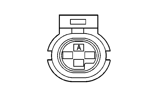
For 1990-2009 cars only
| Table 1: | Engine Oil Pressure Gauge Sensor Connector |
| Table 2: | Instrument Cluster |

| |||||||
|---|---|---|---|---|---|---|---|
Connector Part Information |
| ||||||
Pin | Wire Color | Circuit No. | Function | ||||
A | TAN/WHT | 331 | Oil Pressure Sensor Signal | ||||
B-D | -- | -- | Not Used | ||||

| |||||||
|---|---|---|---|---|---|---|---|
Connector Part Information |
| ||||||
Pin | Wire Color | Circuit No. | Function | ||||
A1 | -- | -- | Not Used | ||||
A2 | TAN/WHT | 331 | Oil Sender Sensor Signal | ||||
A3 | WHT | 121 | Tachometer Signal | ||||
A4 | DK GRN | 389 | Vehicle Speed Signal Input | ||||
A5 | PNK | 1020 | Ignition 3 | ||||
A6 | PPL | 1807 | Class 2 Serial Data | ||||
A7 | PNK | 39 | Ignition 1 | ||||
A8 | PNK | 1020 | Ignition 0 | ||||
A9 | BLK/WHT | 451 | Ground | ||||
A10 | ORN | 340 | Battery Positive Voltage | ||||
A11 | BRN/WHT | 419 | Check Engine Indicator Lamp Input | ||||
A12 | BLK/WHT | 451 | Ground | ||||
B1 | LT BLU/BLK | 1414 | Left Turn Signal Switch Input | ||||
B2 | GRY | 1220 | Dimming Input | ||||
B3 | BLK | 1850 | Ground | ||||
B4-B10 | -- | -- | Not Used | ||||
B11 | DK BLU/WHT | 1415 | Right Turn Signal Switch Input | ||||
B12 | -- | -- | Not Used | ||||
