REVERSE ENGAGEMENT SHIFT NEW SERVICE AND PARTS

Model and Year: 1987 PASSENGER CARS WITH THM 700-R4 TRANSMISSIONS 1987 TRUCKS & VANS WITH THM 700-R4 TRANSMISSIONS
This Bulletin covers changes to the 1987 THM 700-R4 transmission to improve shift feel when REVERSE is selected from any gear range and other new parts in the forward and 3-4 clutch assemblies. These parts changes mean you will have to use new service procedures in this bulletin that are not in the 1987 Service Manual.
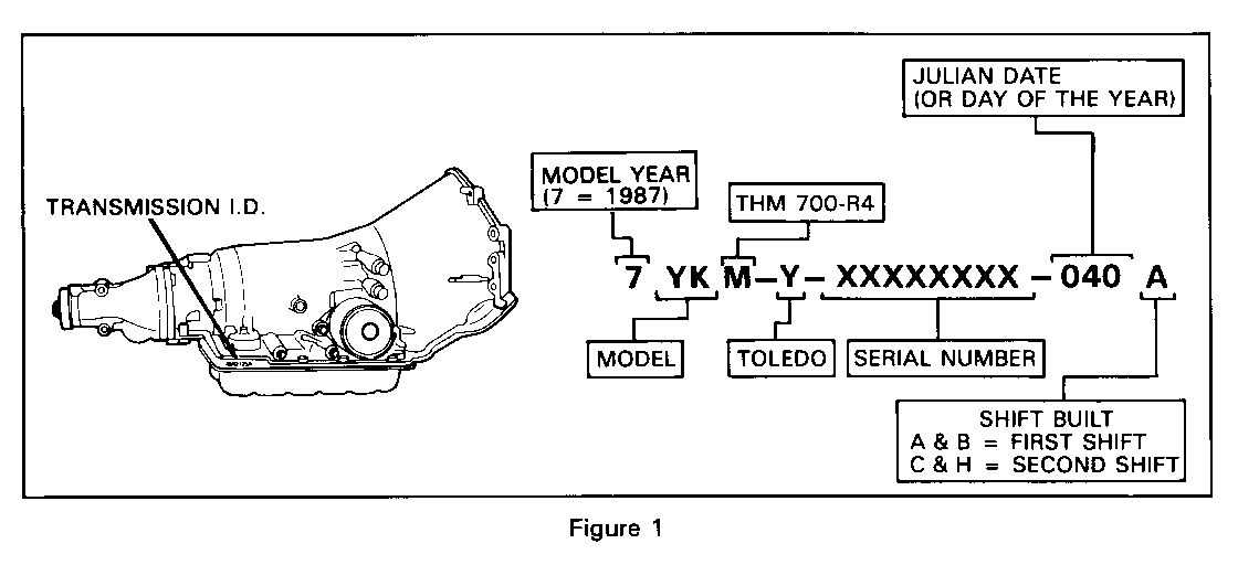
Date of Production Change: (Figure 1) -------------------------- Starting February 9, 1987 (Julian Date 040) all 1987 THM 700-R4 production and Service Replacement Transmission Assembly (SRTA) models were built with new parts in the Reverse, Lo and Reverse, Forward and 3-4 Clutch Assemblies.
Service Action:
Each "SUBJECT" in this bulletin will help you to identify new parts, show how to overhaul the new clutch assemblies and explain which parts can service a 1982-1986-1987 (before Julian Date 040) THM 700-R4 transmission.
Service Parts Information:
Each "SUBJECT" will give the new part numbers and descriptions for each of the subject clutches. It may be necessary to VIP order these new parts from GM Service Parts Operations (GMSPO).
Service Manual Reference:
The 1987 Service Manual procedures can be used to remove the clutch assemblies from the transmission. Use the information in this bulletin to bench overhaul the clutches.
Service Notes:
IMPORTANT: Also use the information in Chevrolet Dealer Service Bulletins 87-56 and 87-107 when assembling any 1987 THM 700-R4 transmission.
TRANSMISSION APPLICATIONS: SUBJECT: ------------------------- ------- 1987 THM 700-R4 (MD8) New Reverse Input Housing And Drum Assembly
TRANSMISSION MODELS:
All Models
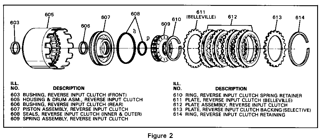
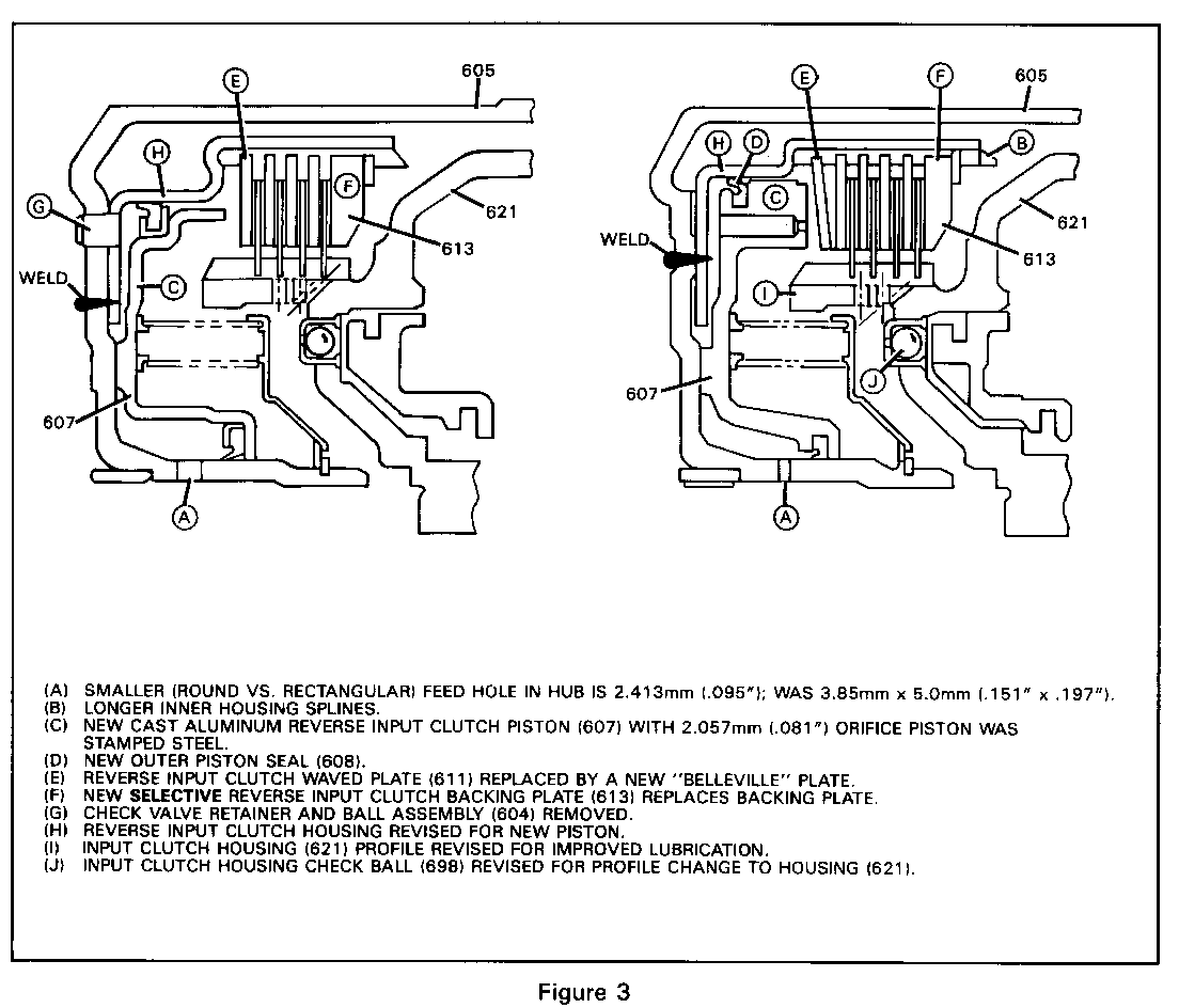
CHANGE TO ASSEMBLY COMPONENTS: (Figures 2 and 3) ----------------------------- New reverse input housing and drum assembly (605) is revised as follows:
o Smaller (round versus rectangular) feed hole in hub is 2.413mm (.095"); was 3.85 x 5.0mm (.151 x .197" ) o Longer inner housing splines o Check valve retainer and ball assembly removed o New cast aluminum reverse input clutch piston (607) with 2.057mm (.081") orifice o Reverse input clutch waved plate (611) replaced by a "belleville" plate o Thinner reverse input clutch fiber plates (612) - thickness now is 1.73-1.88mm (.068-.074"); was 1.93-2.13mm (.076-.084") o Selective reverse input clutch backing plate (613)
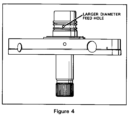
New oil pump cover assembly (217) changed as follows: (Figure 4) o Larger diameter reverse input feed hole in stator hub
SERVICE ACTION:
Component parts of the new reverse and input housing and drum assembly are available through the G.M. Service Parts Organization (GMSPO) catalog. These parts cannot be used with parts from transmissions built prior to February 9, 1987 (Julian Date 040).
SERVICE PARTS INFORMATION:
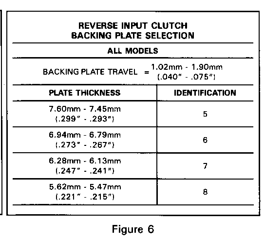
Part Number Description ----------- ----------- 8663068 Reverse Input Clutch Housing And Drum Assembly Complete 8663071 Reverse Input Clutch Piston 8657922 Reverse Input Clutch Seal Package 8663079 Reverse Input Clutch Plate Assembly ******* Pump Cover Assembly (Refer to GMSPO Catalog for Part Numbers and Model Usage) Backing Plate - Reverse Input Clutch 8663075 Identification 5 - Figure 6 8663076 Identification 6 - Figure 6 8663077 Identification 7 - Figure 6 8663078 Identification 8 - Figure 6
SERVICE MANUAL REFERENCE:
1987 Service Manuals do not contain the information found in this bulletin. Use this information when disassembly or assembly of the reverse input housing and drum assembly is required on transmissions built after February 9, 1987 (Julian Date 040).
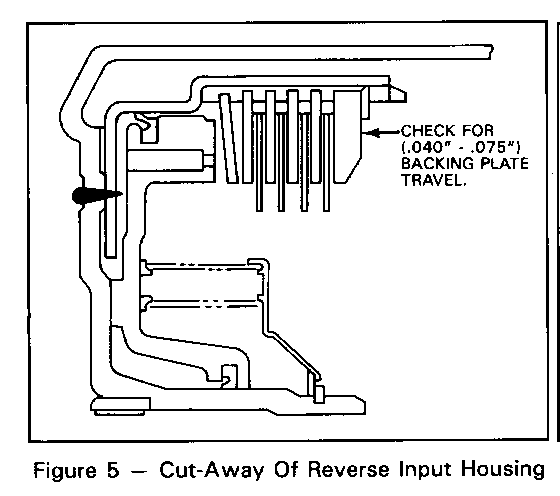
Reverse Input Clutch Backing Plate Selection Procedure (Figures 5 & 6)
1. With the reverse input clutch fully assembled, apply an evenly distributed load to the clutch pack in the direction and diameter as shown in Figure 5. Medium pressure (approx. 20 lbs.) on the backing plate applied by fingers on five evenly distributed points will obtain the backing plate travel for measurement. (CAUTION: Excessive pressure will distart the "belleville" plate resulting in an inaccurate measurement.)
2. Using a feeler gage, measure between the snap ring and the backing plate. Backing plate travel should be 1.02mm-1.90mm (.040"-.075").
3. Select the proper backing plate to obtain the specified travel. (Figure 6)
TRANSMISSION APPLICATIONS: SUBJECT: ------------------------- -------- 1987 THM 700-R4 (MD8) New Lo And Reverse Clutch Assembly
TRANSMISSION MODELS:
All Models
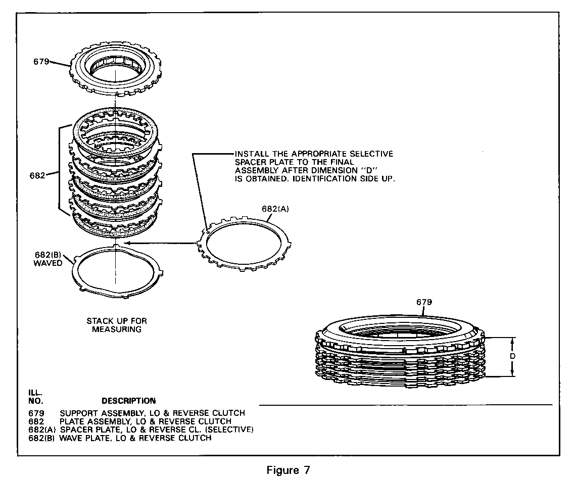
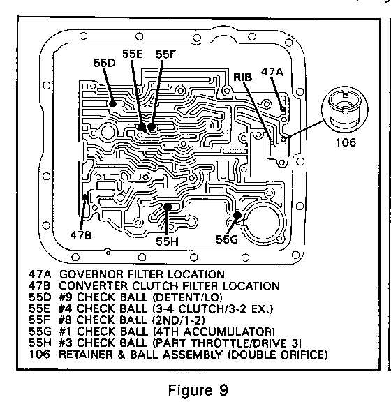
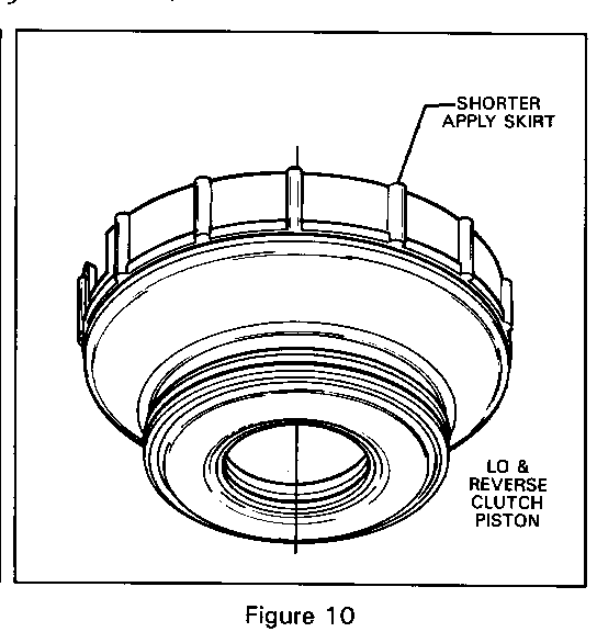
CHANGE TO ASSEMBLY COMPONENTS: (Figures 7, 8, 9 & 10) ----------------------------- New lo and reverse clutch assembly for all models that contain: o New lo and reverse clutch wave plate (682B) o 5 lo and reverse clutch plate assemblies (fiber) o 4 lo and reverse clutch plates (steel) o New selective spacer plate (682A) o New retainer and ball assembly (106) - added to reverse apply passage in rear of case (Figure 9) o New lo and reverse clutch piston with shorter apply skirt (Figure 10)
Procedure for selection of the lo and reverse selective backing plate (Figure 7) 1. On a flat work surface, stack up the following lo and reverse clutch assembly parts: - 1 waved plate - 5 fiber plates and four steel plates (682), starting with one fiber plate and alternating with a steel plate - lo and reverse clutch support assembly (679)
2. Apply an evenly distributed load to the top of the lo and reverse support assembly (679). Light pressure (5 lbs.) on the lo and reverse support assembly (679) will provide the correct dimension for measurement. (CAUTION: Excessive pressure will start to flatten the wave plate resulting in an inaccurate measurement.)
3. Measure height of clutch pack from work surface to the top of lo and reverse clutch support (679). Refer to Figure 7, Dimension D.
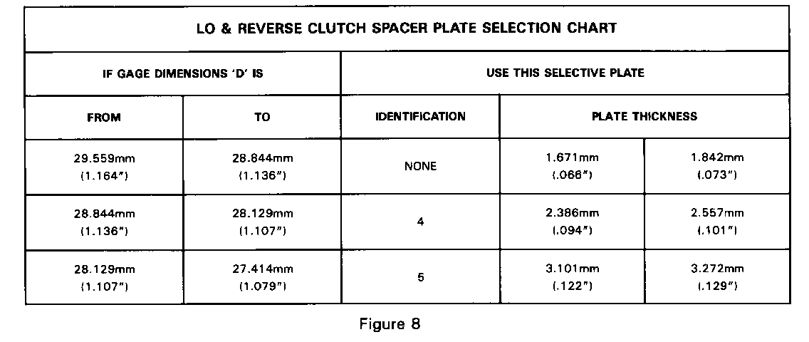
4. Use dimension "D" (Figure 8) to select proper thickness of the selective spacer plate for assembly.
5. Install the proper selective spacer plate between the wave plate and first fiber clutch plate with the identification facing up.
6. The overall height for dimension "D" with the selective spacer plate included should be 30.515mm-31.401mm (1.20"-1.24").
SERVICE ACTION:
The new lo and reverse clutch assembly components may be used on all 1982 through 1987 transmissions only if all the new service parts and procedures for selection of the clutch pack clearance are used during assembly.
SERVICE PARTS INFORMATION:
Part Number Description ----------- ------------ Lo & Reverse Clutch Spacer Plate (Selective) 8667584 Identification 4 - Refer to Figure 8 8667585 Identification 5 - Refer to Figure 8 6261120 Identification None - Refer to Figure 8 8667583 Lo & Reverse Clutch Piston 8648987 Lo & Reverse Clutch Piston Seals 8642472 Lo & Reverse Clutch Plate Assembly (fiber - 5 required) 6261120 Lo & Reverse Clutch Plate (steel - 4 required) 8667048 Lo & Reverse Clutch Wave Plate 8663890 Retainer & Ball Assembly (double orifice)
TRANSMISSION APPLICATIONS: SUBJECT: -------------------------- ------- 1987 THM 700-R4 (MD8) New Forward Clutch Backing Plate
TRANSMISSION MODELS:
All Models
CHANGE TO ASSEMBLY COMPONENTS:
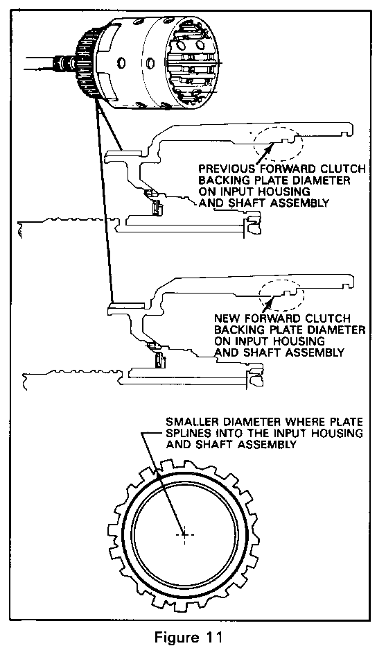
o New forward clutch backing plate is smaller in diameter (Figure 11) o Input housing and shaft assembly with larger splines that match the forward clutch backing plate splines (Figure 11)
SERVICE ACTION:
The new forward clutch backing plate or the new input housing and shaft assembly cannot be used on transmissions built prior to February 9, 1987 (Julian Date 040).
SERVICE PARTS INFORMATION:
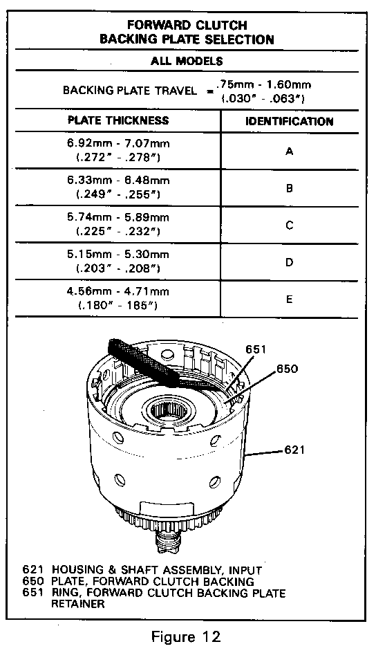
Part Number Description ----------- ----------- Forward Clutch Backing Plate, Selective (650) 8667667 Identification A - Refer to Figure 12 8667668 Identification B - Refer to Figure 12 8667669 Identification C - Refer to Figure 12 8667670 Identification D - Refer to Figure 12 8667671 Identification E - Refer to Figure 12 8667661 Input Housing & Shaft Assembly (621) (used with 245mm converter) 8667659 Input Housing & Shaft Assembly (621) (used with 298mm converter) 8667660 Input Housing & Shaft Assembly (6211 (used with 298mm converter MHM model only)
Procedure for selection of the forward clutch backing plate (Figure 12)
1. With the overrun clutch and the forward clutches fully assembled in the input housing and shaft assembly. Use feeler gages to measure the backing plate travel.
2. Proper forward clutch backing plate travel should be .75mm (.030") to 1.60mm (.063").
3. Select the proper forward clutch backing plate (Figure 12) to obtain the specified travel.
TRANSMISSION APPLICATIONS: SUBJECT: ------------------------- ------- 1987 THM 700-R4 (MD8) New 3-4 Clutch Apply Package
TRANSMISSION MODELS:
All Models
CHANGE TO ASSEMBLY COMPONENTS:
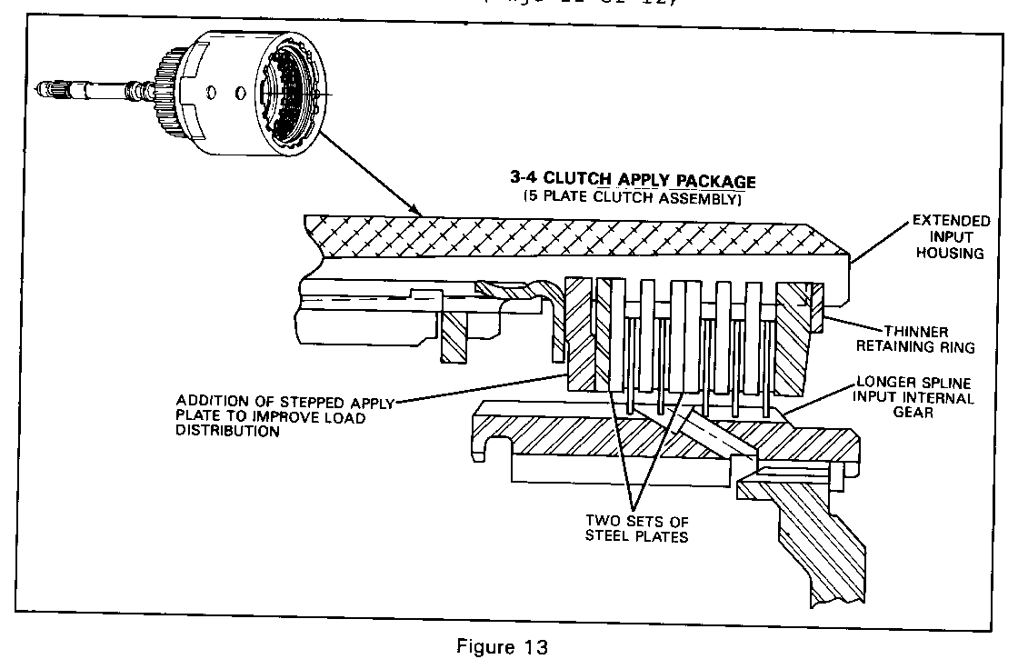
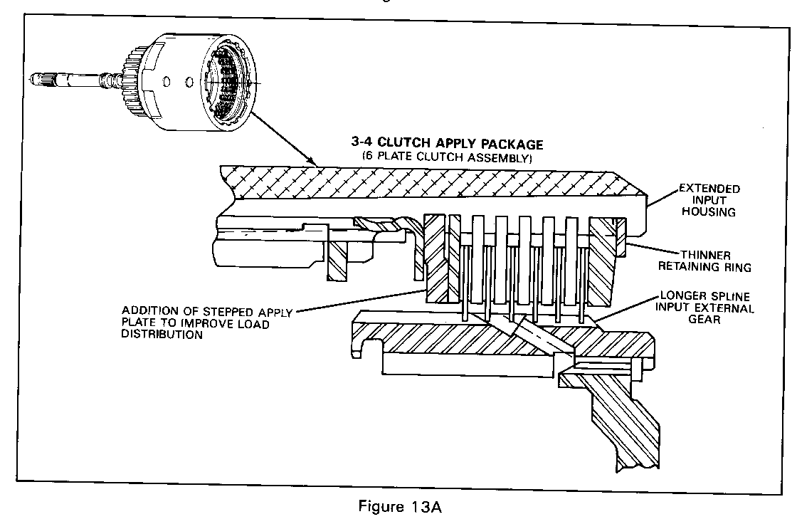
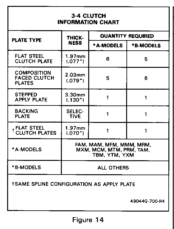
NOTICE: Certain transmissions ("A" Models, Figure 14) will have two steel plates stacked together in two places (one in the middle) to provide the same stack-up as a six plate clutch assembly and to draw heat away from the fiber plates. When assembling the 3-4 clutch, refer to Figures 13, 13A and 14 for proper assembly.
o New 3-4 clutch apply plate "stepped" replacing a "flat" apply plate (Figure 13) o Input housing and shaft assembly revised with longer housing splines for using the new 3-4 clutch apply plate o New input internal gear with longer splines on outside diameter o Eliminate usage of longer 3-4 clutch apply ring (now only using short 3-4 clutch apply ring on all models) o New 3-4 backing plates, (material and thickness) o New internal retaining ring (thinner) and end configuration changed for identification
SERVICE ACTION:
The new 3-4 clutch apply plate or the new input housing and shaft assembly cannot be used on transmissions built prior to February 9, 1987 (Julian Date 040).
SERVICE PARTS INFORMATION:
Part Number Description ---------- ----------- 8642173 Plate, 3-4 Clutch 8667423 3-4 Clutch Apply Plate 8667661 Input Housing & Shaft Assembly (621) (used with 245mm converter) 8667659 Input Housing & Shaft Assembly (621) (used with 298mm converter) 8667660 Input Housing & Shaft Assembly (621) (used with 298mm converter MHM model only) 8663636 Internal Retaining Ring 8663639 Input Internal Gear
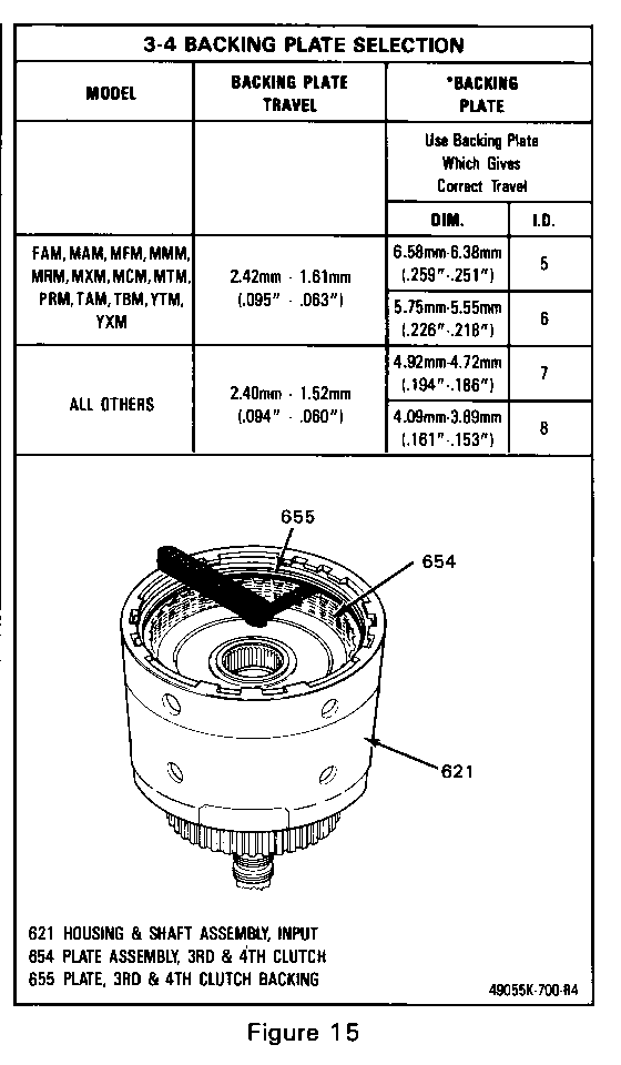
3-4 Clutch Backing Plate Selection Procedure (Figure 15)
1. With the input housing and shaft assembly fully assembled, use a feeler gage to measure for correct backing plate traval (Figure 1 5).
2. Select the proper backing plate to obtain the specified travel (Figure 15).
SERVICE MANUAL REFERENCE:
1987 Service Manuals do not contain the information in this bulletin. Use the procedures and information provided in this bulletin in addition to your Service Manual to service a transmission built after this change.
General Motors bulletins are intended for use by professional technicians, not a "do-it-yourselfer". They are written to inform those technicians of conditions that may occur on some vehicles, or to provide information that could assist in the proper service of a vehicle. Properly trained technicians have the equipment, tools, safety instructions and know-how to do a job properly and safely. If a condition is described, do not assume that the bulletin applies to your vehicle, or that your vehicle will have that condition. See a General Motors dealer servicing your brand of General Motors vehicle for information on whether your vehicle may benefit from the information.
