CAMPAIGN:CYLINDER HEAD BLOCKED INSPECT AND REPLACE HEAD

MODEL AND YEAR: 1986 S/T-10 LIGHT DUTY TRUCK AND ASTRO VAN MODELS EQUIPPED WITH 2.5L L4 GAS ENGINE (RPO LN8)
TO: ALL CHEVROLET DEALERS
This information supplements the service procedure section of Campaign Bulletin 86CI4 issued October, 1986.
SERVICE PROCEDURE
It is necessary to make a probe out of one of the following:
Metal coat hanger - Straightened and cut approximately 12 inches long.
Dipstick - Cut off twisted end.
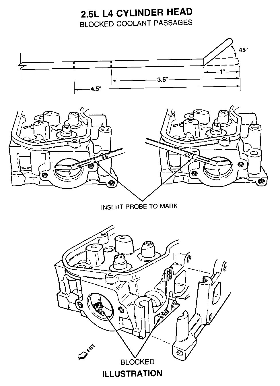
Place a permanent mark 3.5 inches and 4.5 inches from one end of the probe. Then one inch from this same end, put a 45 degree bend in the probe (see Illustration).
S/T TRUCK (WITH OR WITHOUT AIR CONDITIONING): -------------------------------------------- 1. Disconnect battery cable.
2. Drain engine of all coolant. Use a clean container and save the coolant for re-use.
3. Loosen generator adjustment bolts.
4. Remove generator belt.
5. Remove generator adjustment bolts.
6. Disconnect throttle cable at the intake manifold.
7. Remove generator adjustment pivot bracket and lay generator aside.
8. Disconnect coolant sensor wire.
9. Disconnect hose at thermostat housing.
10. Disconnect strut rod bracket at generator front bracket.
11. Remove generator front bracket.
12. Disconnect electrical harness at thermostat.
ITEMS 13 THROUGH 18 APPLY TO TRUCKS EQUIPPED WITH AIR CONDITIONING.
13. Disconnect electrical harness at air conditioning compressor.
14. Remove air conditioning compressor belt.
15. Remove air conditioning compressor bracket.
16. Disconnect air conditioning compressor harness.
17. Remove air conditioning compressor from bracketry and lay aside.
18. Remove air conditioning compressor front support bracket.
19. Disconnect upper radiator hose at thermostat housing.
20. Remove vacuum line bracket from thermostat housing.
21. Remove thermostat housing.
#22.Insert the probe into the two cooling passages (see Illustration).The probe is to be inserted a minimum of 3.5 inches into the right (passenger side) coolant passage and 4.5 inches into the left (driver side) coolant passage. If this can be done no further action is required. Proceed to step 23. If the probe will not slide into one or both passages even after several attempts, the cylinder head must be replaced. Refer to S/T Truck Service Manual, ST-369-86, Section 6AI for removal and installation procedures, then proceed to step 23.
23. Clean the thermostat housing and cylinder head of all old sealant.
24. Apply sealant GM P/N 1052915 or equivalent to the thermostat housing and install to the cylinder head.
25. Reverse steps 1-21 for parts re-installation. Refill cooling system using original coolant. Top off coolant with GM P/N 1052753 or equivalent mixed 50% with water.
26. Install Campaign Identification Label according to instructions contained in this bulletin.
# Denotes change
SPECIFICATIONS
W/A/C W/0 A/C ------ ------- Belt tension (old belts):
Generator 400 N (90 lbs) 300 N (67 lbs) Air conditioning 400 N (90 lbs)
Thermostat Housing Bolts: 27 NM. (20 ft.lbs) 27 NM. (20 ft.lbs)
Generator Mounting torque:
Rear Bolt 27 NM. (20 ft.lbs) 27 NM. (20 ft.lbs) Lower Mounting Bolt 50 NM. (37 ft.lbs) 50 NM. (37 ft.lbs) Adjusting Arm Bolt 27 NM. (20 ft.lbs) 27 NM. (20 ft.lbs)
Compressor Mounting Bolts:
Front 43 NM. (32 ft.lbs) Rear 30 NM. (22 ft.lbs)
M-VAN (WITH OR WITHOUT AIR CONDITIONING):
1. Disconnect battery cable.
2. Drain engine of all coolant. Use a clean container and save the coolant for re-use.
3. Remove air intake and extension duct.
4. Remove oil fill tube.
5. Remove vacuum line bracket.
6. Remove upper radiator hose.
7. Remove generator belt.
8. Disconnect throttle cable at the intake manifold.
9. Remove generator adjustment pivot bracket.
10. Remove generator front bracket.
11. Disconnect hose at thermostat housing.
12. Disconnect electrical harness at thermostat.
# ITEMS 13 THROUGH 15 APPLY TO TRUCKS EQUIPPED WITH AIR CONDITIONING.
# Denotes change
13. Disconnect electrical harness at air conditioning compressor.
14. Remove air conditioning compressor belt.
15. Remove air conditioning compressor bracket.
16. Remove thermostat housing.
#17.Insert the probe into the two cooling passages (see Illustration). The probe is to be inserted a minimum of 3.5 inches into the right (passenger side) coolant passage and 4.5 inches into the left (driver side) coolant passage. If this can be done no further action is required. Proceed to step 18. If the probe will not slide into one or both passages even after several attempts, the cylinder head must be replaced. Refer to the Astro Service Manual, ST-372-86, Section 6AI for removal and installation instructions, then proceed to step 18.
18. Clean the thermostat housing and cylinder head of all old sealant.
19. Apply sealant GM P/N 1052915 or equivalent to the thermostat housing and install to the cylinder head.
20. Reverse steps 1-16 for parts re-installation. Refill cooling system using original coolant. Top off coolant with GM P/N 1052753 or equivalent mixed 50% with water.
21. Install Campaign Identification Label according to instructions contained in this bulletin.
SPECIFICATIONS-
Belt tension (old belts):
Generator 300 N (67 lbs) Air Conditioning 400 N (90 lbs)
Thermostat Housing Bolts: 27 NM. (20 ft.lbs)
Generator Mounting torque:
Top Bracket Bolt 27 NM. (20 ft.lbs) Bottom Bracket Bolt 50 NM. (37 ft.lbs) Nut at back brace 42 NM. (30 ft.lbs)
Compressor Mounting Bolts:
Front 43 NM. (32 ft.lbs) Rear 30 NM. (22 ft.lbs)
# Denotes change

General Motors bulletins are intended for use by professional technicians, not a "do-it-yourselfer". They are written to inform those technicians of conditions that may occur on some vehicles, or to provide information that could assist in the proper service of a vehicle. Properly trained technicians have the equipment, tools, safety instructions and know-how to do a job properly and safely. If a condition is described, do not assume that the bulletin applies to your vehicle, or that your vehicle will have that condition. See a General Motors dealer servicing your brand of General Motors vehicle for information on whether your vehicle may benefit from the information.
