CAMPAIGN: FRONT SHOULDER BELT RETRACTOR-REDUCED SENSITIVITY

SUBJECT: FRONT SHOULDER BELT RETRACTOR
U.S. Campaign Number Cross Reference: Chev Pont 9OC36 Canada Only
Models: Certain 1988 Chevrolet Beretta and certain 1989-90 Chevrolet Corsica/Beretta and Pontiac Tempest with Passive Restraint System
TO: ALL GENERAL MOTORS DEALERS
General Motors of Canada Limited has determined that a defect which relates to motor vehicle safety exists in certain 1988 Chevrolet Beretta and certain 1989-90 Chevrolet Corsica/Beretta and Pontiac Tempest model vehicles. Some of these vehicles may exhibit a condition in which the front shoulder belt retractor may have reduced sensitivity of the lock-up feature. During sudden deceleration, the lock-up feature may not operate properly and the operator and/or front seat passenger may be restrained by only the lap belt. In the event of a vehicle crash or other sudden deceleration, this condition may result in the increased possibility and/or severity of injury to the driver and/or front seat passenger.
To prevent this condition from occurring, dealers are to inspect to determine if the vehicle has a passive (door mounted) or active ("B" pillar mounted) safety belt system. If the vehicle has a passive safety belt system, dealers are to replace the front shoulder belt retractors and belt assemblies.
VEHICLES INVOLVED:
Involved are certain 1988 Chevrolet Beretta and certain 1989-90 Chevrolet Corsica/Beretta and Pontiac Tempest model vehicles built within the following VIN break points:
Plant Year Model Plant Code From Through ---- ----- ----- ----- ---- ------- 1988 Chevrolet Beretta Linden "E" JE568825 JE677985 1988 Chevrolet Beretta Wilmington "Y" JY573204 JY686334 1989 Chevrolet Corsica/Beretta Linden "E" KE100001 KE311038 1989 Chevrolet Corsica/Beretta Wilmington "Y" KY100001 KY300371 1989 Pontiac Tempest Wilmington "Y" KY700004 KY717455 1990 Chevrolet Corsica/Beretta Linden "E" LE100001 LE228156 1990 Chevrolet Corsica/Beretta Wilmington "Y" LY100001 LY266182 1990 Pontiac Tempest Wilmington "Y" LY700002 LY712469
All affected vehicles have been identified by the VIN listing provided to involved dealers with this bulletin. Any dealer not receiving a listing was not shipped any of die affected vehicles.
DEALER CAMPAIGN RESPONSIBILITY:
Dealers are to perform this campaign on all involved vehicles at no charge to owners, regardless of kilometres traveled, age of vehicle, or ownership, from this time forward.
Whenever a vehicle subject to this campaign is taken into your new or used vehicle inventory, or it is in your dealership for service, you are to ensure the campaign correction has been made before selling or releasing the vehicle.
Owners of vehicles recently sold from your new vehicle inventory are to be contacted by the dealer, and arrangements made to make the required modification according to instructions contained in this bulletin.
CAMPAIGN PROCEDURE:
Refer to Section 4 of the Service Policies and Procedures Manual for the detailed procedure on handling Product Campaigns. Dealers are requested to complete the campaign on all transfers as soon as possible.
OWNER NOTIFICATION:
All owners of record at the time of campaign release are shown on the attached computer listing and have been notified by first class mail from General Motors. The listings provided are for campaign activity only and should not be used for any other purpose.
PARTS INFORMATION:
Parts required to complete this campaign should be ordered through regular channels, as follows:
Part Number Description Quantity/Vehicle ----------- ----------- ---------------- 12515769 Kit - Coupe LH & RH Shoulder Belts & Retractors 1 Sapphire - With Comfort Feature
12515770 Kit - Sedan LH & RH Shoulder Belts & Retractors 1 Sapphire - No Comfort Feature
12515771 Kit - Sedan LH & RH Shoulder Belts & Retractors 1 Sapphire - With Comfort Feature 12515772 Kit - Coupe LH & RH Shoulder Belts & Retractors 1 Medium Beechwood - With Comfort Feature
12515773 Kit - Sedan LH & RH Shoulder Belts & Retractors 1 Medium Beechwood - No Comfort Feature
12515774 Kit - Sedan LH & RH Shoulder Belts & Retractors 1 Medium Beechwood - With Comfort Feature
12515775 Kit - Coupe LH & RH Shoulder Belts & Retractors 1 Garnet Red - With Comfort Feature
12515776 Kit - Sedan LH & RH Shoulder Belts & Retractors 1 Garnet Red - No Comfort Feature
12515777 Kit - Sedan LH & RH Shoulder Belts & Retractors 1 Garnet Red - With Comfort Feature
12515778 Kit - Coupe LH & RH Shoulder Belts & Retractors 1 Medium Dark Gray - With Comfort Feature
12515779 Kit - Sedan LH & RH Shoulder Belts & Retractors 1 Medium Dark Gray - No Comfort Feature
12515780 Kit - Sedan LH & RH Shoulder Belts & Retractors 1 Medium Dark Gray - With Comfort Feature
12515781 Kit - Coupe LH & RH Shoulder Belts & Retractors 1 Black - With Comfort Feature
12515782 Kit - Sedan LH & RH Shoulder Belts & Retractors 1 Black - With Comfort Feature
PARTS AND LABOUR CLAIM INFORMATION:
Credit for the campaign work performed will be paid upon receipt of a properly completed campaign claim card or DCS transmission in accordance with the following:
Repair Code Description Time Allowance ----------- ----------- -------------- 1A Inspect - Vehicle has an Active Belt System .3 - No Further Action Required
2A Replace Both Front Seat Shoulder Belt 1.2 Retractors - Coupe (all with comfort feature)
3A Replace Both Front Seat Shoulder Belt 1.5 Retractors - Sedan (without comfort feature)
4A Replace Both Front Seat Shoulder Belt 1.5 Retractors - Sedan (with comfort feature)
Time allowance includes 0. 1 hour for dealer administrative detail associated with this campaign. Parts credit will be based on dealer net plus 30% to cover parts handling.
SERVICE PROCEDURE:
NOTICE: ALL DEALERS ARE BEING SENT AN INSTRUCTIONAL VIDEO TAPE ILLUSTRATING THIS PROCEDURE. THIS VIDEO TAPE WILL BE IN A BLUE SLEEVE AND LABELLED "1988-1990 L-CAR SHOULDER BELT RETRACTOR REPLACEMENT PROCEDURE." BE CERTAIN TO VIEW THIS VIDEO TAPE PRIOR TO PERFORMING THE MODIFICATION PROCEDURE.
THERE IS NO MENTION OF PONTIAC TEMPEST IN THE VIDEO, HOWEVER USE THE CHEVROLET CORSICA MODIFICATION PROCEDURE.
INSPECTION
Inspect vehicle for the presence of an active or passive safety belt system. On vehicles equipped with active belt systems, the front lap and shoulder belt retractors are located in the "B" pillar (or front door striker pillar) and the shoulder belt upper guide loop is attached to the top of the "B" pillar. On vehicles equipped with passive belt systems, the front lap and shoulder belt retractors are located in the front doors and the shoulder belt upper guide loop is attached to the door in the upper rear comer of the front door glass opening.
If the vehicle is found to have a passive safety belt system (door mounted), proceed with the modification procedure portion of the bulletin.
If the vehicle is found to have an active safety belt system ("B" pillar mounted), do not attempt to perform the modification procedure. Apply a Campaign Identification Label and retum to the vehicle to the owner.
MODIFICATION PROCEDURE:
BERETTA (COUPE)
1. Place a clean mat or other protective material on floor under area where door will be open and worked on.
2. Lower window to full open position. Make sure ignition is in OFF position.
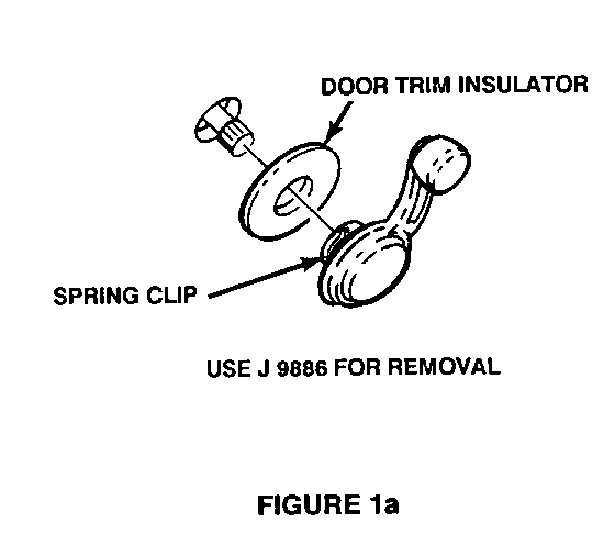
3. For vehicles without power windows, remove window regulator handle (window crank) using tool J-48-86 (Figure 1a).
NOTICE: Note position of window crank so it may be reinstalled in same position.
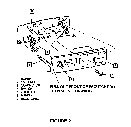
4. Remove one (1) Phillips head screw from door handle escutcheon. Pull out on forward end of escutcheon to disengage long, push-in retainer; then pull escutcheon forward to clear retaining tab on rear of escutcheon (Figure 2).
5. On vehicles equipped with power door locks, disconnect power door lock connector.
NOTICE: The following steps describe the procedure to be followed for removal of door trim panel. It is important that proper tools and procedures be used to avoid damage to trim panels.
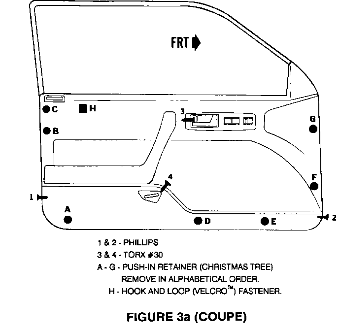
6. Remove two (2) Phillips head screws from locations #1 and #2 (Figure 3a).
7. Remove two (2) #30 torx head screws from locations #3 and #4 (Figure 3a).
8. Disengage seven (7) push-in ("Christmas tree") retainers which hold door trim panel to door sheet metal at locations A through G (Figure 3a) using tool J-24595B. It is very important that the specified tool be used to disengage "Christmas tree" retainers, and that this procedure is performed carefully. Use of improper tools or technique may result in damage to door trim panel.
9. Disengage hook-and-loop (velcro) fastener at location H (Figure 3a) by carefully pulling door trim panel away from door.
10. After top of door trim panel has been pulled out from under lip at bottom of door glass opening, remove shoulder belt escutcheon from top of trim panel. Door trim panel should now be free of door except for lap belt.
11. Carefully rotate and lower trim panel so front edge of trim panel is resting on protective mat placed on floor in Step 1 and so panel is leaning against door.
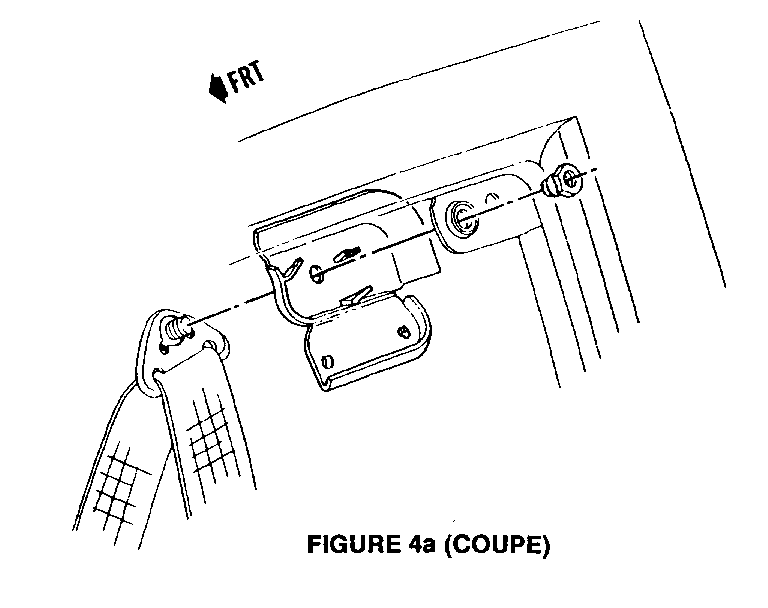
12. Open hinged cover on shoulder belt guide loop located in upper, rear corner of door. Cover opens from top and is hinged on bottom (Figure 4a).
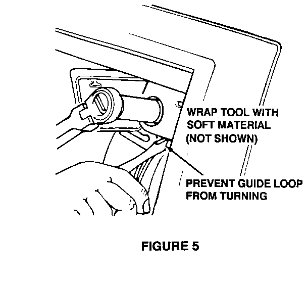
13. Remove shoulder belt guide loop from door with an 18mm socket and using a screwdriver wrapped in soft, protective covering to prevent guide loop from rotating while loosening nut (Figure 5).
NOTICE: Save guide loop nut for re-use when installing new shoulder belt retractor assembly.
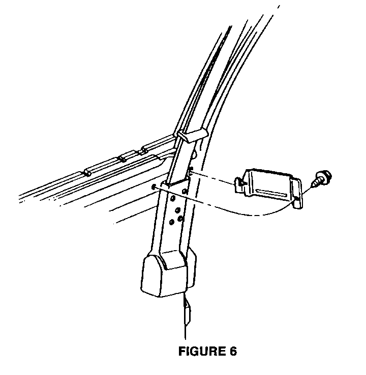
14. Remove shoulder belt web guide from door by removing one (1) #30 torx screw from front end of guide and disengaging rear tab of guide from door (Figure 6).
15. Disconnect wire harness from shoulder belt retractor.
16. Open hinged cover to comfort feature cable on shoulder belt retractor (this cover opens from top and is hinged on bottom) and disconnect comfort feature cable from retractor.
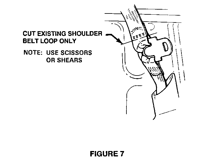
17. Carefully cut only shoulder belt webbing from latch plate where illustrated in Figure 7. It is recommended that scissors or shears be used to reduce risk of damage to lap belt webbing or to latch plate.
NOTICE: It is very important to use extreme care when cutting shoulder belt webbing from latch plate. If lap belt webbing is damaged in any way while cutting shoulder belt webbing, lap belt and retractor assembly will have to be replaced also.
Latch plates on some vehicles may be equipped with a white plastic belt webbing protector. Do not remove or damage this protector.
18. Remove shoulder belt retractor using the following procedure:
A. Remove one (1) Phillips head screw at top of retractor.
B. Remove one (1) 15mm nut at bottom of retractor.
C. Remove retractor assembly (retractor, shoulder belt webbing, guide loop assembly from upper rear comer of door, and shoulder belt escutcheon removed from door trim panel will not be reused).
19. Install replacement shoulder belt retractor assembly using the following procedure:
NOTICE: Use care when handling replacement shoulder belt retractor assemblies. Rough and/or careless handling could result in damage to retractor assembly, belt webbing, guide loop, or belt escutcheon.
A. Position retractor assembly over lower mounting stud and align upper attaching screw hole with hole in door.
B. Install one (1) Phillips head screw at top of retractor. Tighten to 5 N.m (4 lb. ft.).
C. Install one (1) 15mm nut at bottom of retractor. Tighten to 42 N.m (31 lb. ft.).
20. Apply thread locking compound to threads of guide loop stud bolt. Use Loctite 242 thread locking compound (P/N 12345382) or equivalent.
21. Position guide loop in upper rear corner of door, making certain shoulder belt webbing is flat (not twisted) from retractor assembly up to guide loop. Install one (1) 18mm nut to guide loop and tighten to 23 N.m (17 lb. ft.) with an 18mm socket and using a screwdriver wrapped in a soft, protective covering to prevent guide loop from rotating while tightening nut (Figure 5). Close guide loop plastic cover.
22. Insert tab at rear of shoulder belt web guide into door slot and position guide over belt webbing. Install one (1) #30 torx screw to web guide and tighten to 5 N.m (3.7 lb. ft.). See Figure 6.
23. Connect wiring harness to new shoulder belt retractor.
24. Open cover of splitter box on new shoulder belt retractor (cover opens from top and is hinged at bottom).
25. Make certain comfort feature cable is properly routed behind shoulder belt retractor sleeve and connect "T" end of cable to comfort mechanism in splitter box. Insert cable barrel into retainer clip in splitter box. Close cover to splitter box.
NOTICE: Proper connection of comfort feature cable must be verified to avoid additional, unnecessary labour later in this procedure.
26. Position door trim panel to begin reinstallation to door. Before inserting top edge of trim panel under lip at bottom of door glass opening, install shoulder belt escutcheon to trim panel; then insert door trim panel under lip at bottom of door glass opening. DO NOT apply pressure to seat any push-in ("Christmas tree,") retainers at this time. Door trim panel installation will be completed only after proper shoulder belt function is verified. Only apply slight pressure at hook-and-loop (velcro) fasteners location to temporarily hold panel in position.
27. Check lap belt to ensure it is not twisted inside trim panel by pulling lap belt all the way out and carefully letting it spool back up onto retractor so latch plate is still accessible. Do not allow lap belt and latch plate to be pulled completely inside of trim panel.
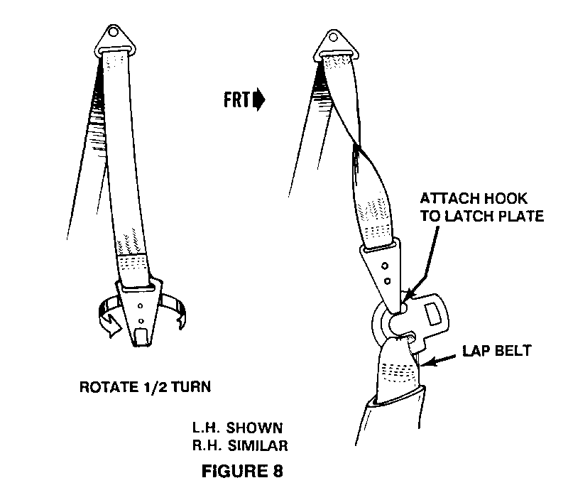
28. With door closed, temporarily fasten new shoulder belt (with chrome hook on end of it) to latch plate using the following procedure (Figure 8):
A. With shoulder belt hanging down flat (no twists) from guide loop at top of door, twist hook at end of shoulder belt 1/2 turn, so rearward edge of hook rotates toward centre of vehicle and ends up as front edge.
B. Position hook at end of shoulder belt onto latch plate along with lap belt. Compare twist of shoulder belt with other, up-repaired, side. They should be symmetric (mirror images) to each other.
C. Additionally, check belt assembly for proper twist by sitting in driver/passenger seat and buckling lap/shoulder belt. Hook on end of shoulder belt should be facing up when buckled. An incorrect twist in shoulder belt will be very obvious when seated with belt assembly on and buckled.
D. If there is any question about orientation of new shoulder belt, consult instructional video for clarification.
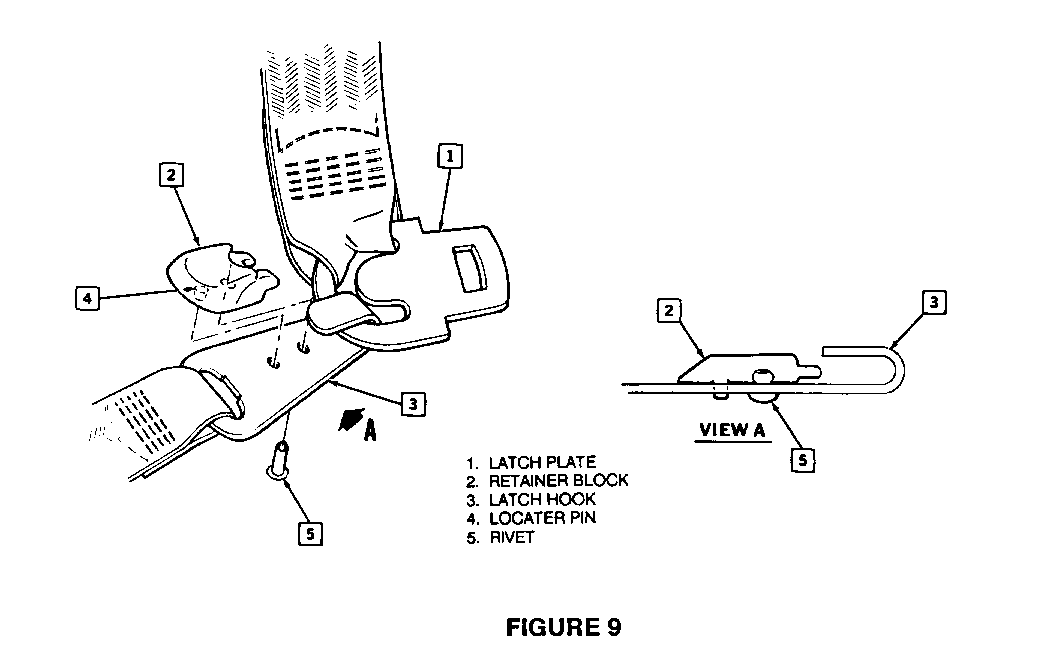
29. When new shoulder belt hook is properly oriented and hooked to latch plate, position retainer block/insert onto shoulder belt hook and secure insert to hook using special pop rivet supplied with kit (Figure 9).
30. Before completing installation of door trim panel, check function of comfort feature. Sit in vehicle with lap/shoulder belt fastened and door completely closed. Pull three to four inches of additional shoulder belt webbing out from retractor and let it in very slowly.
A. If comfort feature is working, retractor should stop rewinding webbing before belt is snug against occupant, leaving some slack for "comfort." When lap/shoulder belt is unbuckled, the lap belt, but not the shoulder belt, should retract. When door is opened, the shoulder belt should retract.
B. If comfort feature is not working, make certain door is completely closed, and not ajar. If door is completely closed, it will be necessary to remove door trim panel and recheck comfort feature cable connection in splitter box of newly-installed shoulder belt retractor. If comfort feature cable is properly connected, proceed with complete installation of door trim panel; a procedure to install a spacer to repair comfort feature is described in Step 40.
31. Position door trim panel to begin reinstalling it to door. Before inserting top edge of trim panel under lip at bottom of door glass opening, install shoulder belt escutcheon to trim panel; then insert door trim panel under lip at bottom of door glass opening. After making sure door trim panel is properly aligned to door, apply moderate pressure at hook-and-loop (velcro) fastener location to temporarily hold panel in position. Apply adequate pressure to seat the seven (7) push-in ("Christmas tree") retainers.
32. Reinstall two (2) Phillips head screws to door trim panel at locations shown in Figure 3a. Tighten to 1.9 N.m (1.4 lb. ft.).
33. Reinstall one (1) #30 torx fastener to door trim panel at rear of door latch opening (Figure 3a). Tighten to 9.5 N.m (7.0 lb. ft.).
34. Reinstall one (1) #30 torx fastener to door trim panel at rear of map pocket (Figure 3a). Tighten to 9.5 N.m (7.0 lb. ft.).
35. Position door handle escutcheon to door trim panel (Figure 2).
36. For vehicles equipped with power door locks, reconnect door lock connector to power door lock switch on door handle escutcheon (Figure 2).
37. Position door handle escutcheon to door trim panel. Properly align door lock rod with door lock slide, and then locate and seat long, push-in retainer on front of escutcheon (Figure 2).
38. Install one (1) Phillips head screw to door handle escutcheon (Figure 2). Tighten to 1.9 N.m (1.4 lb. ft.).
39. On vehicles without power windows, reinstall window regulator handle (window crank) and door trim insulator, making sure handle is aligned in same position as prior to removal. Install retaining clip using tool J-9886 (Figure 1).
40. If comfort feature failed to work properly after checking for correct cable connection at retractor and making sure door was not ajar, a shim from campaign kit must be installed to body of vehicle at location where comfort release plunger in door contacts the body:
A. Determine exact location where comfort release plunger contact body of vehicle. There should be a wear mark on the body at this location. If there is no wear mark, apply masking tape to body approximately where plunger makes contact, and coat end of plunger with a marking material such as a grease pencil and shut door. Plunger contact location should then be visible.
B. Drill a 6.30mm (1/4 in.) hole in body at plunger contact location. Apply primer and paint to exposed sheet metal, and install a push-in spacer from campaign parts kit using body sealer to prevent moisture intrusion.
41. Repeat check for comfort feature function (Step Number 30).
42. Repeat above procedure (Steps 1 through 41) for opposite side front shoulder belt retractor assembly.
43. Install Campaign Identification Label.
CORSICA/TEMPEST (SEDAN) ----------------------- 1. Place a clean mat or other protective material on floor under area where door will be open and worked on.
2. Lower window to full open position. Make sure ignition is in OFF position.
3. On vehicles without power windows, remove window regulator handle (window crank) using tool J-9886 (Figure 1a).
NOTICE: Note position of window crank so it can be reinstalled in same position.
4. For vehicles with power windows, use the following procedures to disconnect and remove power window switches from door trim panel:
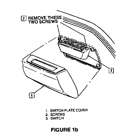
Driver's Side Door: ------------------- A. Remove switch plate cover by grasping cover at bottom and lifting upward and inward at the same time (Figure 1b).
B. Remove two (2) Phillips screws which secure switch to trim panel (Figure 1b).
C. Remove switch by disconnecting it from wire harness connector (Figure 1b).
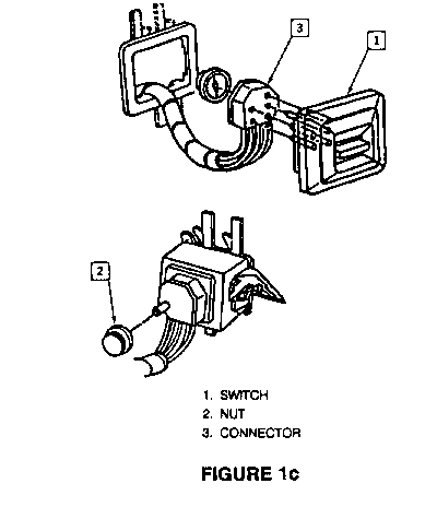
Passenger's Side Door: ---------------------- Power window switch on passenger side door is not to be removed from door trim panel for this procedure. However, switch must be disconnected from wiring harness connector in order to remove passenger's side door trim panel from vehicle (Figure 1c).
5. Remove one (1) Phillips head screw from door handle escutcheon. Pull out on forward end of escutcheon to disengage long, push-in retainer; then pull escutcheon forward to clear retaining tab on rear of escutcheon (Figure 2).
6. On vehicles equipped with power door locks, disconnect power door lock connector.
NOTICE: The following steps describe the procedure to be followed for removal of door trim panel. It is important that proper tools and procedures be used to avoid damage to trim panels.
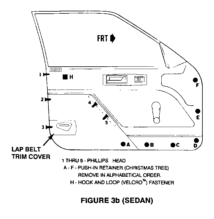
7. Remove three (3) Phillips head screws from locations #1, #2 and #3 (Figure 3b).
8. Carefully disengage lap belt trim cover from lap belt and remove it from door trim panel. Set aside for reinstallation later (Figure 3b).
9. Remove two (2) Phillips head screws from armrest pull cup (locations #4 and #5) and remove cup (Figure 3b).
10. Disengage six (6) push-in ("Christmas tree") retainers which hold door trim panel to door sheet metal at locations A through F (see Figure 3b) using tool J-24595B. It is very important that specified tool be used to disengage "Christmas tree" retainers, and that this procedure is performed-carefully. Use of improper tools or technique may result in damage to door trim panel.
11. Disengage hook-and-loop (velcro) fastener at location H (see Figure 3b) by carefully pulling door trim panel away from door.
12. After top of door trim panel has been pulled out from under lip at bottom of door glass opening, remove shoulder belt escutcheon from top of trim panel.
13. On passenger side door of vehicles with power windows, carefully pull trim panel away from door and disconnect power window switch from wire harness connector. Refer to Step #3 above and see Figure 1c.
14. Door trim panel should now be completely free of door and should be carefully set aside for later reinstallation.
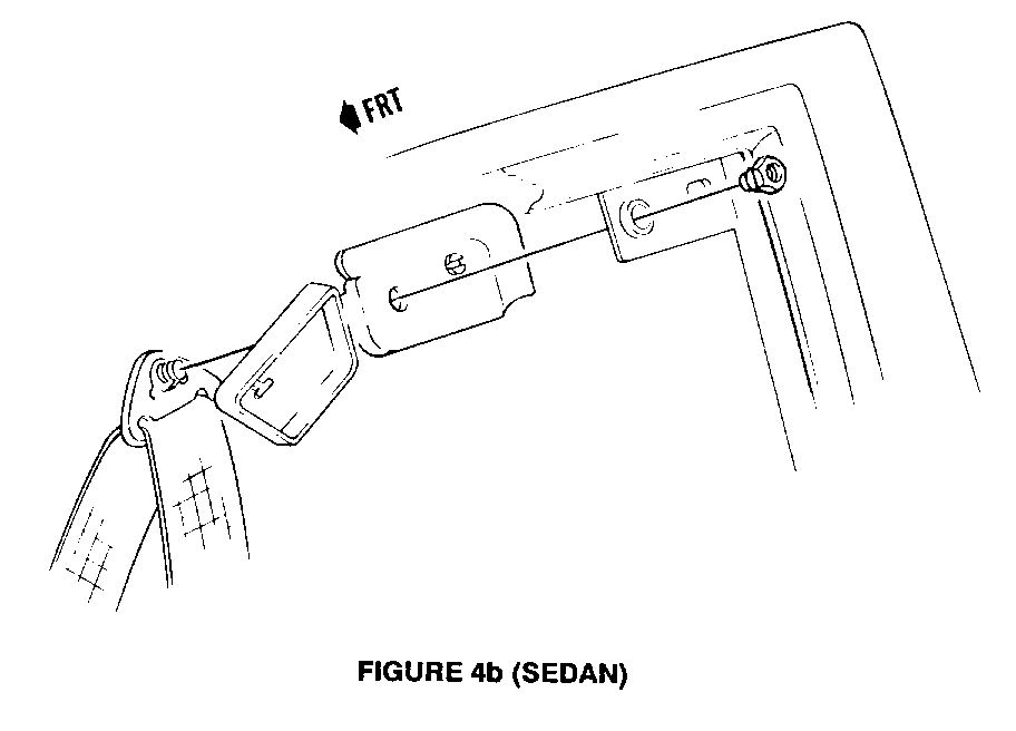
15. Open hinged cover on shoulder belt guide loop located in upper, rear comer of door. Cover opens from front and is hinged at rear (Figure 4b).
16. Remove shoulder belt guide loop from door with an 18mm socket and using a screwdriver wrapped in soft, protective covering to prevent guide loop from rotating while loosening nut (Figure 5, Page 13).
NOTICE: Save guide loop nut for re-use later when installing new shoulder belt retractor assembly.
17. Remove shoulder belt web guide from door by removing one (1) #30 torx screw from front end of guide and disengaging rear tab of guide from door (Figure 6).
18. Disconnect wire harness from shoulder belt retractor.
19. On those vehicles with comfort feature shoulder belts, open hinged cover to comfort feature cable on shoulder belt retractor (cover opens from top and is hinged on bottom) and disconnect comfort feature cable from retractor.
20. Carefully cut only shoulder belt webbing from latch plate where illustrated in Figure 7. It is recommended that scissors or shears be used to reduce risk of damage to lap belt webbing or to latch plate.
NOTICE: It is very important to use extreme care when cutting shoulder belt webbing from latch plate. If lap belt webbing is damaged in my way while cutting shoulder belt webbing, lap belt and retractor assembly will have to be replaced also.
Latch plates on some vehicles may be equipped with a white plastic belt webbing protector. Do not remove or damage this protector.
21. Remove shoulder belt retractor using the following procedure:
A. Remove one (1) Phillips head screw at top of retractor.
B. Using a screwdriver or other appropriate tool, pry back the backing plate retaining tabs.
C. Remove one (1) 15mm nut at bottom of retractor.
D. Loosen, but do not remove, two (2) 15mm nuts from lap belt retractor. The nuts must be loose enough to allow retractor backing plate to tilt out far enough to allow bottom of shoulder belt retractor to clear bottom mounting stud.
E. Remove retractor assembly (retractor, shoulder belt webbing, guide loop assembly from upper rear comer of door, and shoulder belt escutcheon removed from door trim panel will not be reused).
NOTICE: Use care when handling replacement shoulder belt retractor assemblies. Rough and/or careless handling could result in damage to retractor assembly, belt webbing, guide loop, or belt escutcheon.
22. Install new replacement shoulder belt retractor assembly using the following procedure:
A. Position retractor assembly over lower mounting stud, making certain bottom of retractor assembly is under tab on retractor backing plate.
B. Align upper attaching screw hole with hole in retractor backing plate and install one (1) Phillips head screw at top of retractor. Tighten to 5 N.m (4 lb. ft.).
C. Push retractor backing plate tabs down over shoulder belt retractor.
D. Install one (1) 15mm nut at bottom of shoulder belt retractor. Tighten to 42 N.m (31 lb. ft.).
E. Tighten two lap belt retractor nuts to 42 N.m (31 lb. ft.).
23. Apply thread locking compound to threads of guide loop stud bolt. Use Loctite 242 thread locking compound (P/N 12345382) or equivalent.
24. Position guide loop in upper rear comer of door, making certain shoulder belt webbing is flat (not twisted) from retractor assembly up to guide loop. Install one (1) 18mm nut to guide loop and tighten to 23 N.m (17 lb. ft.) with an 18mm socket and using a screwdriver wrapped in a soft, protective covering to prevent guide loop from rotating while tightening nut (Figure 5). Close guide loop plastic cover.
25. Insert tab at rear of shoulder belt web guide into door slot and position guide over belt webbing. Install one (1) #30 torx screw to web guide and tighten to 5 N.m (3.7 lb. ft.). See Figure 6.
26. Connect wiring harness to new shoulder belt retractor.
27. For those vehicles equipped with comfort feature shoulder belts, open cover of splitter box on new shoulder belt retractor (cover opens from top and is hinged at bottom).
28. For those vehicles equipped with comfort feature shoulder belts, make certain comfort feature cable is properly routed and connect "T" end of cable to comfort mechanism in splitter box. Insert cable barrel into retainer clip in splitter box. Close cover to splitter box.
NOTICE: Proper connection of comfort feature cable must be verified to avoid additional, unnecessary labour later in this procedure.
29. With door closed, temporarily fasten new shoulder belt (with chrome hook on end of it) to latch plate using the following procedure (Figure 8):
A. With shoulder belt hanging down flat (no twists) from guide loop at top of door, twist hook at end of shoulder belt 1/2 turn, so rearward edge of hook rotates toward centre of vehicle and ends up as front edge.
B. Position hook at end of shoulder belt onto latch plate along with lap belt. Compare twist of shoulder belt with other, up-repaired, side. They should be symmetric (mirror images) to each other.
C. Additionally, check belt assembly for proper twist by sitting in driver/passenger seat and buckling lap/shoulder belt. Hook on end of shoulder belt should be facing up when buckled. An incorrect twist in shoulder belt will be very obvious when seated with belt assembly on and buckled.
D. If there is any question about orientation of new shoulder belt, consult instructional video for clarification.
30. When new shoulder belt hook is properly oriented and hooked to latch plate, position retainer block/insert onto shoulder belt hook (Figure 9) and secure insert to hook using special pop rivet supplied with kit.
31. Before installing door trim panel, check function of comfort feature on vehicles so equipped. Sit in vehicle with lap/shoulder belt fastened and door completely closed. Pull three to four inches of additional shoulder belt webbing out from retractor and let it back in very slowly.
For vehicles equipped with comfort feature belts:
A. If comfort feature is working, retractor should stop rewinding webbing before belt is snug against occupant, leaving some slack for "comfort." When lap/shoulder belt is unbuckled, the lap belt, but not the shoulder belt, should retract. When door is opened, the shoulder belt should retract.
B. If comfort feature is not working, make sure door is completely closed, and not ajar. If door is completely closed, it will be necessary to re-check comfort feature cable connection in splitter box of newly-installed shoulder belt retractor. If comfort feature cable is properly connected, proceed with installation of door trim panel; a procedure to install a spacer to repair comfort feature is described in Step 46.
32. Position door trim panel to begin reinstalling it to door by properly positioning lap belt into opening in trim panel.
33. On driver's side door of vehicles with power windows, position power window switch harness connector so power window switch can be reconnected to harness after trim panel is installed (Figure 1b).
34. For passenger's side door of vehicles with power windows, reconnect power window switch to power window harness connector (Figure 1c).
35. Before inserting top edge of trim panel under lip at bottom of door glass opening, install shoulder belt escutcheon to trim panel; then insert door trim panel under lip at bottom of door glass opening. After making certain door trim panel is properly aligned to door, apply moderate pressure at hook-and-loop (velcro) fastener location to temporarily hold panel in position. Apply adequate pressure to seat the six (6) push-in ("Christmas tree") retainers (Figure 3b).
36. Reinstall lap belt trim cover with one (1) Phillips head screw at location #3 (Figure 3b. Tighten to 1.9 N.m (1.4 lb. ft.).
37. Reinstall two (2) Phillips head screws to door trim panel at locations #1 and #2 (Figure 3b. Tighten to 1.9 N.m (1.4 lb. ft.).
38. Reinstall one (1) #30 torx fastener to door trim panel at rear of door latch opening (Figure 3b). Tighten to 9.5 N.m (7.0 lb. ft.).
39. Position armrest pull cup and reinstall two (2) Phillips head screws (Figure 3b). Tighten to 1.9 N.m (1.4 lb. ft.).
40. For driver's side door of vehicles with power windows, reconnect power window switch to wire harness connector, and reinstall switch to trim panel using two (2) Phillips head screws. Tighten until secure. Reinstall power window switch plate cover (Figure 1b).
41. Position door handle escutcheon to door trim panel.
42. On vehicles equipped with power door locks, reconnect door lock connector to power door lock switch on door handle escutcheon (Figure 2).
43. Position door handle escutcheon to door trim panel. Properly align door lock rod with door lock slide, and locate and seat long, push-in retainer on front of escutcheon (Figure 2).
44. Install one (1) Phillips head screw to door handle escutcheon (Figure 2). Tighten to 1.9 N.m (1.4 lb. ft.).
45. For vehicles without power windows, reinstall window regulator handle (window crank) and door trim insulator, making sure handle is aligned in same position it was in prior to removal. Install retaining clip using tool J-9886 (Figure 1a).
46. For those vehicles equipped with comfort feature shoulder belts, if comfort feature failed to work properly after checking for correct cable connection at retractor and making sure door was not ajar, a shim from campaign kit must be installed to body of vehicle at location where comfort release plunger in door contacts body:
A. Determine exact location where comfort release plunger contact body of vehicle. There should be a wear mark on the body at this location. If there is no wear mark, apply some masking tape to body approximately where plunger makes contact, and coat end of plunger with a marking material (such as a grease pencil) and shut door. Plunger contact location should then be visible.
B. Drill a 6.30mm (1/4 in.) hole in body at plunger contact location. Apply primer and paint to exposed sheet metal, and install a push-in spacer from campaign parts kit using body sealer to prevent moisture intrusion.
47. Repeat check for comfort feature function (Step Number 3l).
48. Repeat above procedure (Steps 1 through 47 above) for opposite side front shoulder belt retractor assembly.
49. Install Campaign Identification Label.
INSTALLATION OF CAMPAIGN IDENTIFICATION LABEL
Clean surface of radiator upper mounting panel and apply a Campaign Identification Label. Make sure the correct campaign number is inserted on the label. This will indicate that the campaign has been completed.
VEHICLE RECALL NOTICE
Dear General Motors Customer.
General Motors of Canada Limited has determined that a defect which relates to motor vehicle safety exists in certain 1988 Chevrolet Beretta and certain 1989-90 Chevrolet Corsica/Beretta and Pontiac Tempest model vehicles. Some of these vehicles may exhibit a condition in which the front shoulder belt retractor may have reduced sensitivity of the lock-up feature. During sudden deceleration, the lock-up feature may not operate properly and the operator and/or front seat passenger may be restrained by only the lap belt. In the event of a vehicle crash or other sudden decleration, this condition may result in the increased possibility and/or severity of injury to the driver and/or front seat passenger.
To prevent this condition from occurring, dealers are to inspect to determine if the vehicle has a passive (door mounted) or active ("B" pillar mounted) safety belt system. If the vehicle has a passive safety belt system, dealers are to replace the front shoulder belt retractors and belt assemblies.
Please contact your GM dealer as soon as possible to arrange a service date.
If parts are required, ask your dealer for details regarding their availability. If parts are not in stock, they can be ordered before scheduling your service date.
This letter identifies your vehicle. Presentation of this letter to your dealer will assist their Service personnel in completing the necessary correction to your vehicle in the shortest possible time.
Subsequent to contacting your dealer, further assistance, if required, may be obtained from our Customer Assistance Centre, toll free, by calling 1-800-263-3777 (English), or 1-800-263-7854 (French).
We are sorry to cause you this inconvenience; however, we have taken this action in the interest of your continued satisfaction with our products.
General Motors bulletins are intended for use by professional technicians, not a "do-it-yourselfer". They are written to inform those technicians of conditions that may occur on some vehicles, or to provide information that could assist in the proper service of a vehicle. Properly trained technicians have the equipment, tools, safety instructions and know-how to do a job properly and safely. If a condition is described, do not assume that the bulletin applies to your vehicle, or that your vehicle will have that condition. See a General Motors dealer servicing your brand of General Motors vehicle for information on whether your vehicle may benefit from the information.
