For 1990-2009 cars only
Removal Procedure
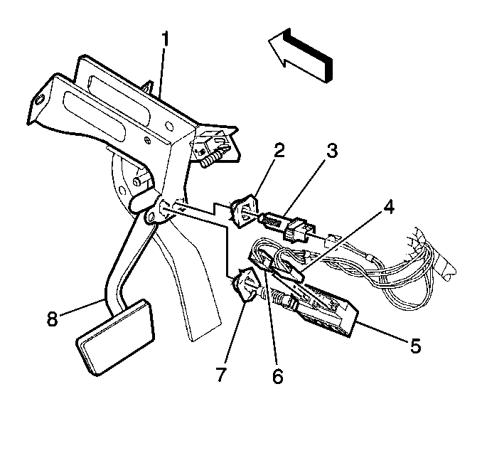
- Remove the driver side sound insulator.
- Remove the electrical connection.
- Remove the brake switch (3), by grasping the brake switch and turning it 90 degrees counter clockwise while pulling toward the rear of the vehicle.

Installation Procedure
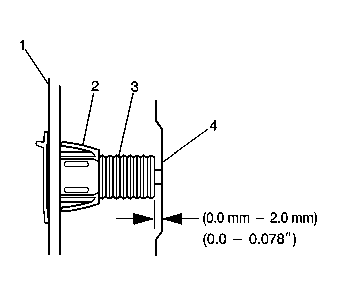
- Insert the stop lamp switch (3) into the retainer until the switch body is seated on the retainer.
- Pull the brake pedal upward against the internal pedal stop.
- Turn the switch 90 degrees clockwise in order to lock the switch into position.
- Connect the electrical connector.
- Adjust the stoplamp switch (3). Refer to Stop Lamp Switch Adjustment .
- Install the driver's side sound insulator.


